Dual Cyclone Dust-Collecting Apparatus Vacuum Cleaner
a dust-collecting apparatus and dual-cyclone technology, applied in the direction of auxillary pretreatment, cleaning filter means, separation processes, etc., can solve the problems of large-scale dual-cyclone dust-collecting apparatus not being used, troublesome to dump dust from the dust-collecting chamber, and difficult to confirm an amount of dust from the outside. , to achieve the effect of short height, increasing flow passage sectional area, and increasing inhalation for
Active Publication Date: 2010-09-09
SAMSUNG ELECTRONICS CO LTD
View PDF11 Cites 125 Cited by
- Summary
- Abstract
- Description
- Claims
- Application Information
AI Technical Summary
Benefits of technology
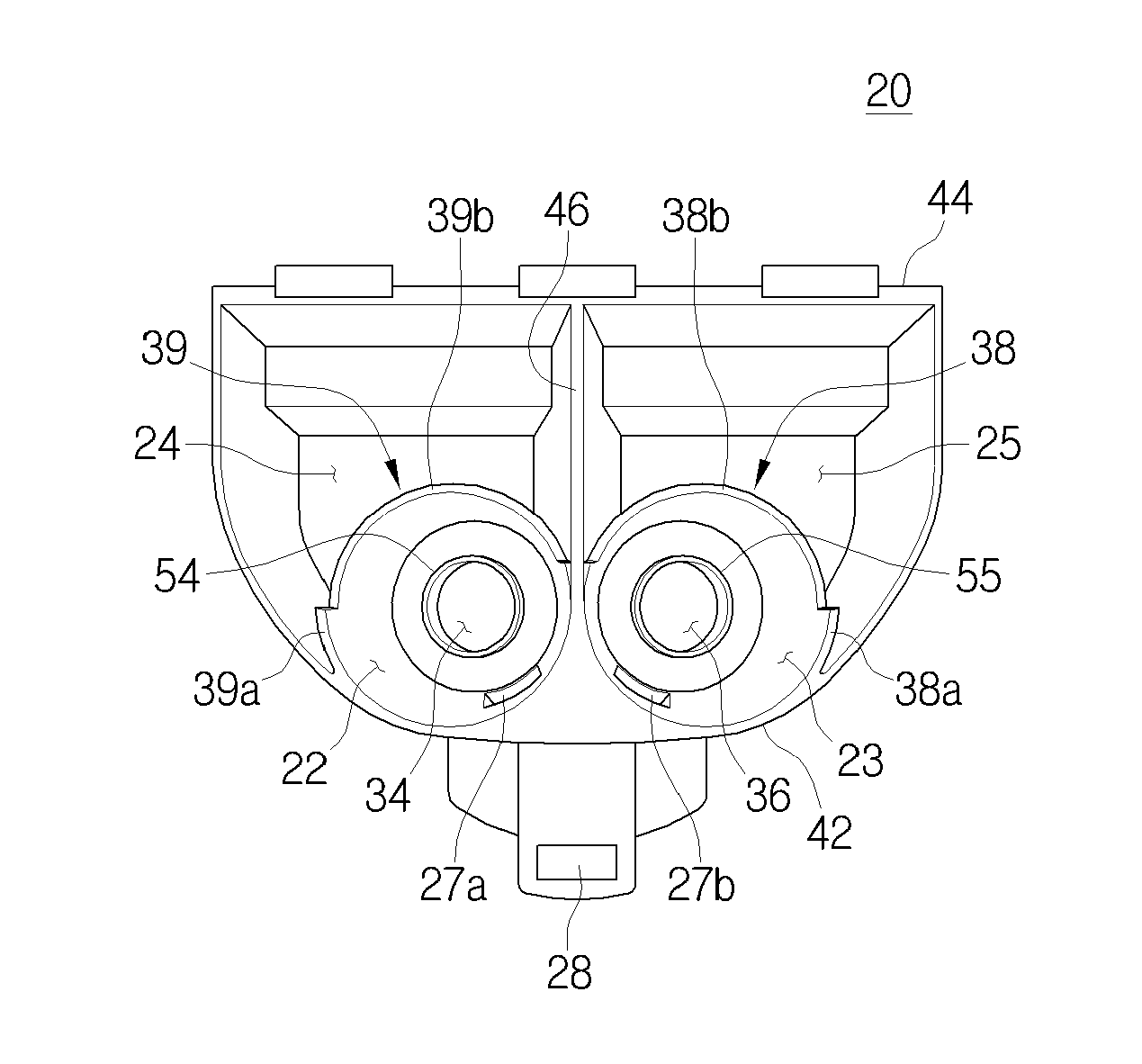
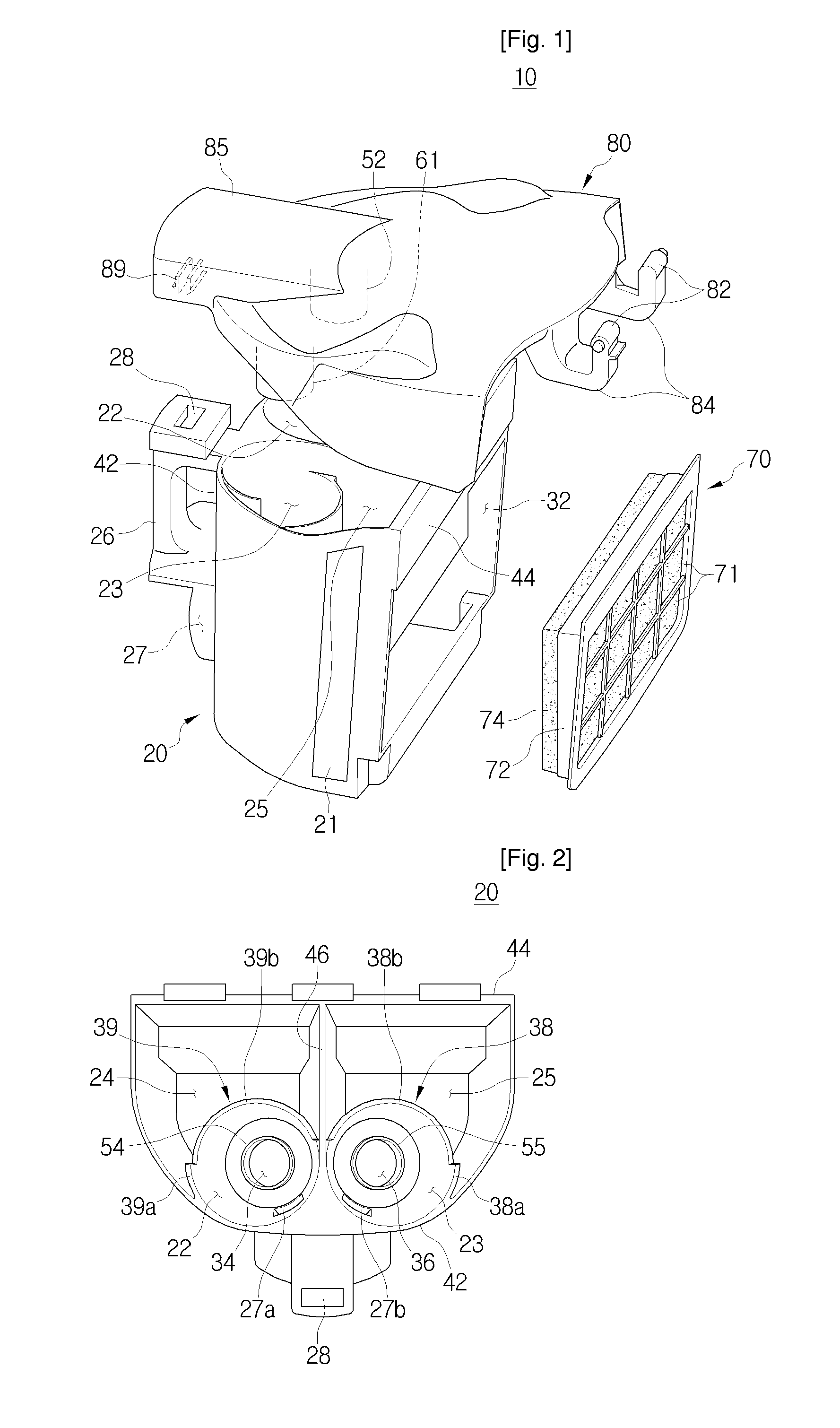
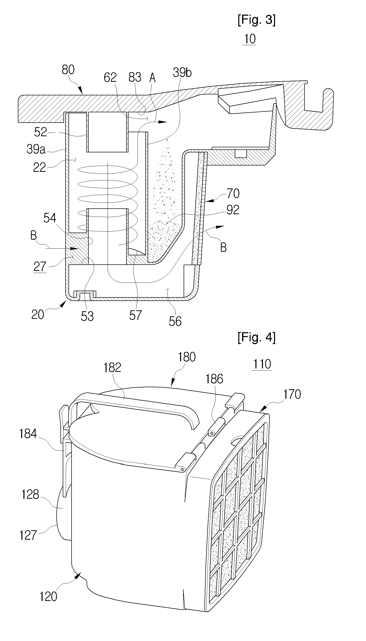
[0015]As described above, according to an aspect of the present invention, the dual cyclone dust-collecting apparatus is configured, so that the two cyclone chambers and the two dust-collecting chambers are disposed in parallel. Accordingly, the dual cyclone dust-collecting apparatus according to the exemplary embodiments of the present invention has a structure, which is compacted and short in height.
[0016]Further, the dual cyclone dust-collecting apparatus is configured, so that the two cyclone chambers are disposed in parallel, thereby increasing a sectional area of flowing passage, and the air is drawn in to the lower parts of the cyclone chambers and then discharged in the same direction as the gravity, thereby increasing the inhalation force. Accordingly, the dust separating or collecting efficiency is improved.
[0017]Also, the dual cyclone dust-collecting apparatus includes the single cyclone body in which the two cyclone chambers and the two dust-collecting chambers are integrally formed by the injection molding. Accordingly, the dual cyclone dust-collecting apparatus according to the exemplary embodiments of the present invention comes to be compacted, and the number of the assembling processes is reduced, thereby increasing the productivity.
[0018]Also, the dual cyclone dust-collecting apparatus includes the cyclone body having the portion formed of the transparent material, thereby easily confirming the amount of dust collected in the dust-collecting chambers from the outside.
Problems solved by technology
However, such a large size dual cyclone dust-collecting apparatus is not used in the present time, since it is too large and inconvenient to use and has a complicated structure.
Also, it is difficult to separate the dust-collecting chamber from the dual cyclone dust-collecting apparatus, and thus it is troublesome to dump dust from the dust-collecting chamber.
Also, if the dual cyclone dust-collecting apparatus does not have a separate electrical measuring device installed therein, it is difficult to confirm an amount of dust from the outside.
Method used
View moreImage
Smart ImageViewing Examples
Examples
Embodiment Construction
INDUSTRIAL APPLICABILITY
[0049]The present invention is applicable to a dust-collecting apparatus, more particularly, a dual cyclone dust-collecting apparatus, which draws in an external air and then separates dust or dirt therefrom.
Sequence List Text
[0050]
Login to View More PUM
| Property | Measurement | Unit |
|---|---|---|
| Force | aaaaa | aaaaa |
Abstract
A dual cyclone dust-collecting apparatus of a vacuum cleaner is disclosed. The dust-collecting apparatus includes an air inlet through which an external air is drawn in, two cyclone chambers into which the external air drawn in through the air inlet air is drawn in, the two cyclone chamber being disposed in parallel, at least one dust-collecting chamber divided in parallel with respect to the two cyclone chambers, and two air outlets through which the external air from the two cyclone chambers is discharged. The air inlet is formed between the two cyclone chambers at a lower part of a cyclone body and the two air outlets are formed in bottom surfaces of the two cyclone chambers, respectively, so that the external air is drawn in through lower parts of one sides of the two cyclone chambers and then discharged through the bottom surfaces of the two cyclone chambers.
Description
TECHNICAL FIELD[0001]The present invention relates to a dust-collecting apparatus, and more particularly, to a dual cyclone dust-collecting apparatus, which draws in an external air and then separates dust or dirt therefrom.BACKGROUND ART[0002]A cyclone dust-collecting apparatus, which whirls an external air and separates dirt from the external air using a centrifugal, has been used from long time ago. Particularly, a dual cyclone dust-collecting apparatus, which two sub-cyclone dust-collecting apparatus are installed in parallel to improve a dust separating or Collecting efficiency, is also known already.[0003]A large size dual cyclone dust-collecting apparatus is disclosed by Dyson et al. in EP patent publication No. 0018197. Two sub-cyclone dust-collecting apparatus of a large size are arranged in an upright type vacuum cleaner. However, such a large size dual cyclone dust-collecting apparatus is not used in the present time, since it is too large and inconvenient to use and has ...
Claims
Login to View More Application Information
Patent Timeline
 IPC IPC(8): B01D45/12
CPCA47L9/1641A47L9/1683A47L9/1666A47L9/16A47L9/10
Inventor OH, JANG-KEUNHAN, JUNG-GYUN
Owner SAMSUNG ELECTRONICS CO LTD
Features
- R&D
- Intellectual Property
- Life Sciences
- Materials
- Tech Scout
- Unparalleled Data Quality
- Higher Quality Content
- 60% Fewer Hallucinations
Learn More Browse by: Latest US Patents, China's latest patents, Technical Efficacy Thesaurus, Application Domain, Technology Topic, Popular Technical Reports.
© 2025 PatSnap. All rights reserved.Legal|Privacy policy|Modern Slavery Act Transparency Statement|Sitemap|About US| Contact US: help@patsnap.com


