

Beverage filtering system
a filtering system and beverage technology, applied in the field of beverages preparation, can solve problems such as the back pressure of the filter, and achieve the effect of preventing further unwanted filtration
- Summary
- Abstract
- Description
- Claims
- Application Information
AI Technical Summary
Benefits of technology
Problems solved by technology
Method used
Image

Examples
second embodiment
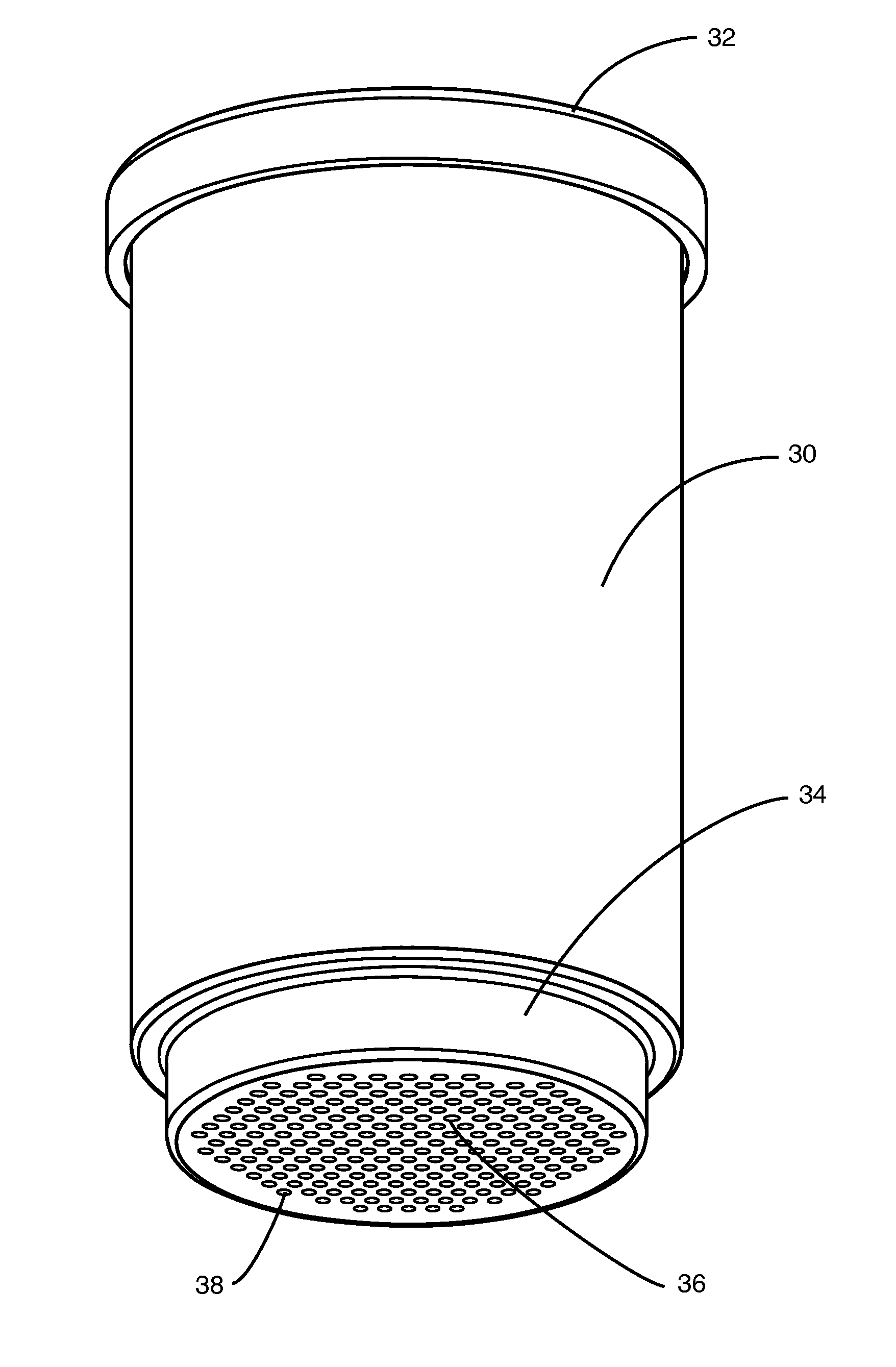
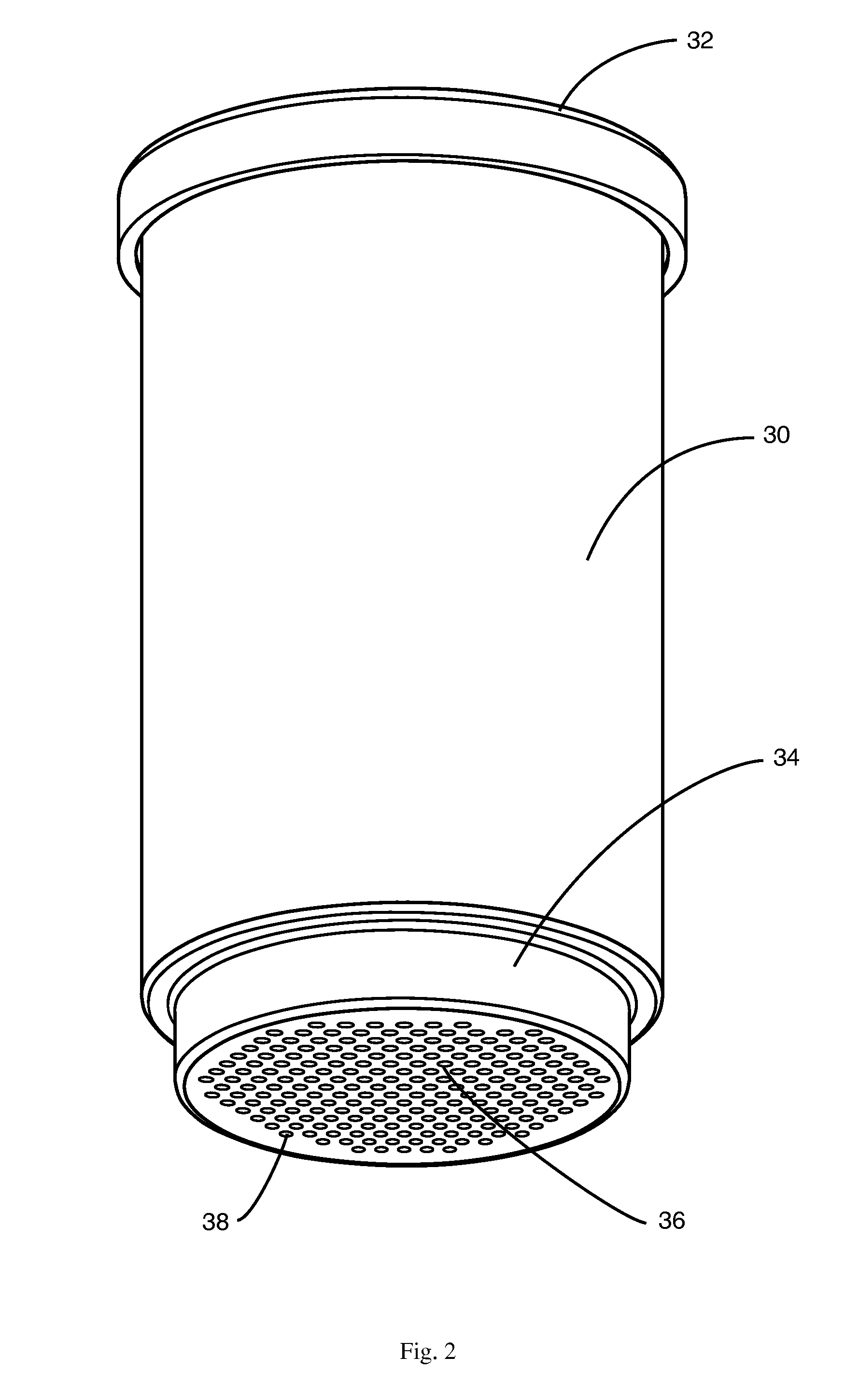
[0064]FIGS. 8E through 8H illustrate the variety of ways in which the filter may be provided in this FIG. 8E is a cross-sectional view of an inner cup 130 having a filter 136 formed by perforations in the very bottom of the inner cup. The perforations are as described above. An enlarged view of this variant is shown in FIG. 9.
[0065]Referring to FIG. 9, inner cup 130 has filter 136 in the bottom thereof as shown. Sealing gasket 134 contacts the inner surface of the outer cup 120 creating a seal of the type described above. In addition to sealing gasket 134, sleeve 132 is integrally formed with an optional rim stopper 138, so called because it limits the amount by which the inner cup 130 may be inserted into the outer cup 120 when it abuts against the rim of the outer cup 120. Sleeve 132, together with integrally formed sealing gasket 134 and optional rim stopper 138, is preferably formed from an elastomeric material, such as a silicone rubber.
[0066]FIG. 8F is a cross-sectional view ...
third embodiment
[0068]the beverage filtering system of the present invention is illustrated in FIGS. 12A through 12E. Referring first to FIG. 12A, system 200 has an outer cup 220 having a bottom portion 224 which is removable. As shown in FIG. 12D, bottom portion 224 may be screwed off of outer cup 220 to remove used ground coffee 56 or the like therefrom.
[0069]Inner cup 230 has a sleeve 232 integrally formed with a sealing gasket 234. Sleeve 232 is as described above. Inner cup 230 flares outwardly at the top to accommodate lid 250, which may be snapped thereon. A plan view of lid 250 is shown in FIG. 12E.
[0070]When the inner cup 230 is pushed down into outer cup 220 during the preparation of a beverage, as shown in FIG. 12B, the bottom of the inner cup 232 and sealing gasket 234 presses the material, such as ground coffee 56 against the bottom of the outer cup 220. Subsequently, the bottom portion 224 is removed, and the inner cup 230 is pushed all the way down to its flared top, enabling the sea...
fourth embodiment
[0071]the beverage filtering system of the present invention is illustrated in FIG. 13. System 300 has an outer cup 320 and an inner cup 330, which is within the outer cup 320 in the cross-sectional view of FIG. 13. Filter 336, which may be perforated as previously described, is at the bottom of the inner cup 330. O-ring 342, which may be of an elastomeric material, such as silicone rubber, is secured between retaining rings 344, which may be of stainless steel, at the lower end of the inner cup 330. O-ring 342, as above, seals the space between the inner cup 330 and the outer cup 320. Inner cup 330 has an outward flare 338 at its upper end. Below the outward flare 338 is an O-ring 346, which functions as a rim stopper for limiting the amount by which the inner cup 330 may be inserted into the outer cup 320.
PUM
 Abstract
Description
Claims
Application Information