
Self-fastening sewer tap

Inactive Publication Date: 2006-06-13
PLASTIQUES GYF LTEE (CA)
View PDF8 Cites 9 Cited by
  • Summary
  • Abstract
  • Description
  • Claims
  • Application Information

AI Technical Summary

Benefits of technology

[0004]Another object of the present invention is to provide a tap which is cheap to mass produce.
[0005]A further object of the present invention is to provide a tap which prevents the filtration encountered with poured concrete seals.
[0006]Still another object of the present invention is to provide a tap which is flexible in order to prevent the same from cracking due to the weight of the ground below the pipes.
[0007]Another object of the present invention is to provide a tap which conveniently locks the branch pipe within the main pipe.
[0010]Preferably, the cylindrical body has an inner wall provided with a peripheral recess forming a vacuum chamber around the branch pipe when the branch pipe is inserted in the tap. Such avoids unwanted removal of the branch pipe from the tap by accident or due to water flow.
[0011]Preferably, also the flexible lip has a truncated cone shape to help ensure watertightness at a junction of the main pipe with the cylindrical body.

Problems solved by technology

Since the connection between the branch and the main pipes is often underground, it is subjected to breakage due to the weight of the soil above and around the connection, which results in an undesired filtration.
Although alternative methods and various mechanical apparatus, such as saddles, are available, they are very costly to implement and must be specially adapted for each situation.
However, using saddles for complex constructions are not usually suitable for connecting the branch pipe to the main pipe because of the difficulties of building a really accurate connection underground (e.g. an excavation after uncovering an existing main pipe).
Moreover, rigid support usually provided by saddle connection may also result in possible breakage and undesired filtration.

Method used


Image

  • Self-fastening sewer tap
  • Self-fastening sewer tap
  • Self-fastening sewer tap

Examples


Embodiment Construction

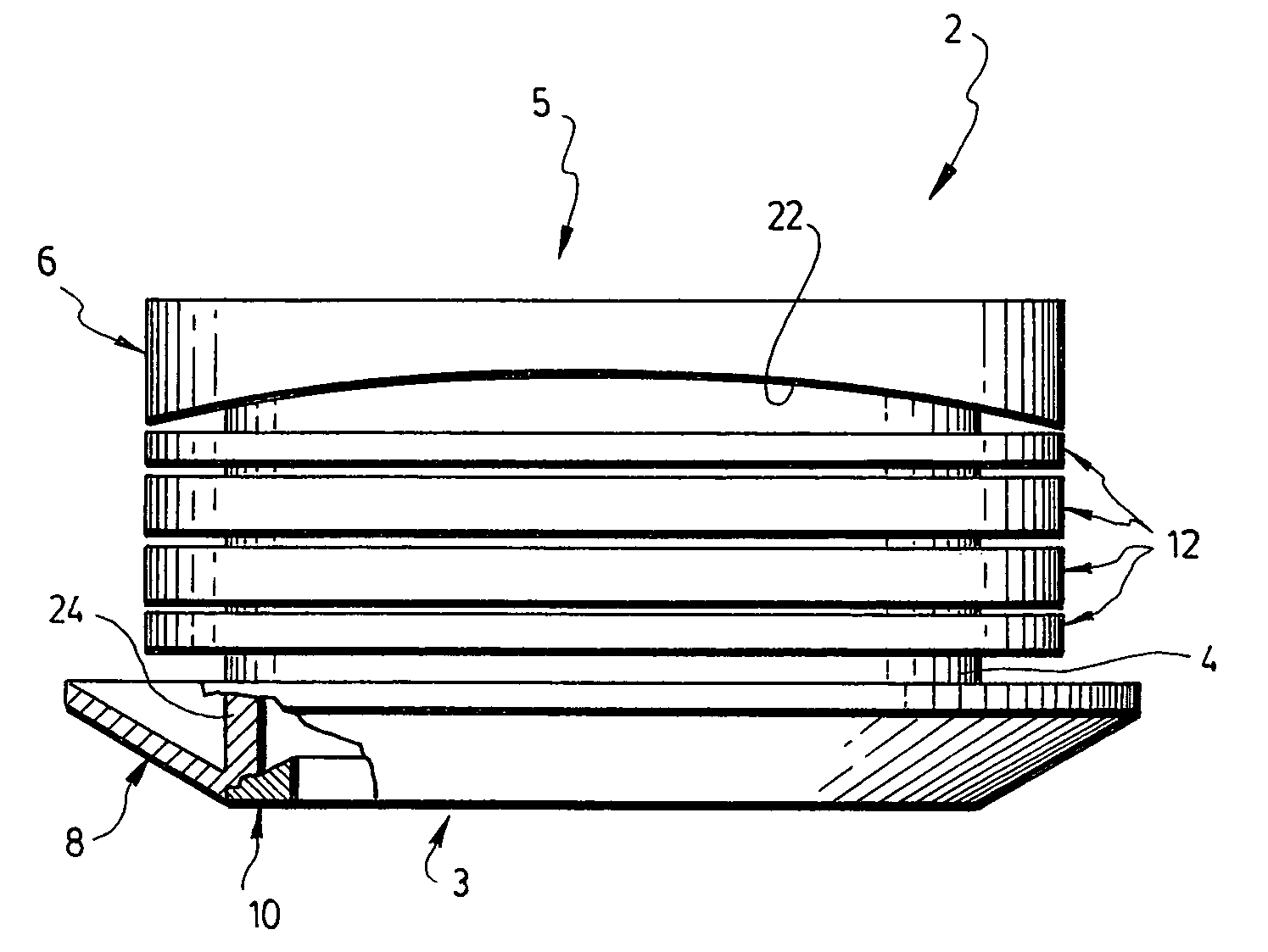
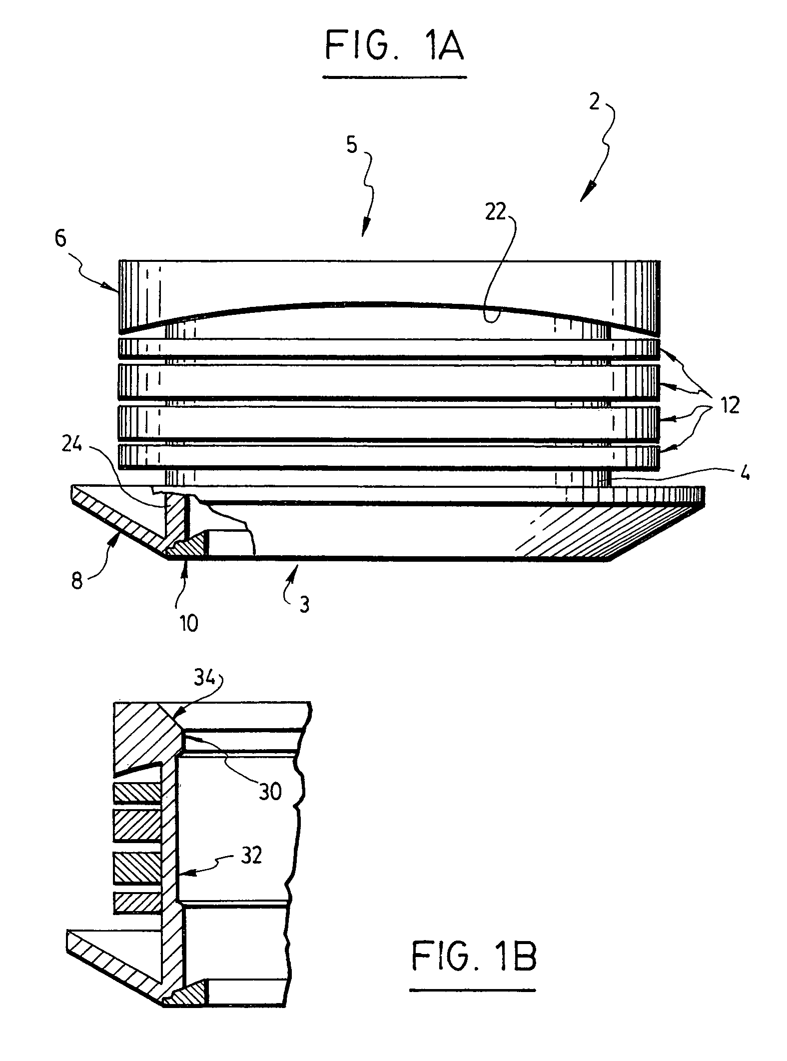
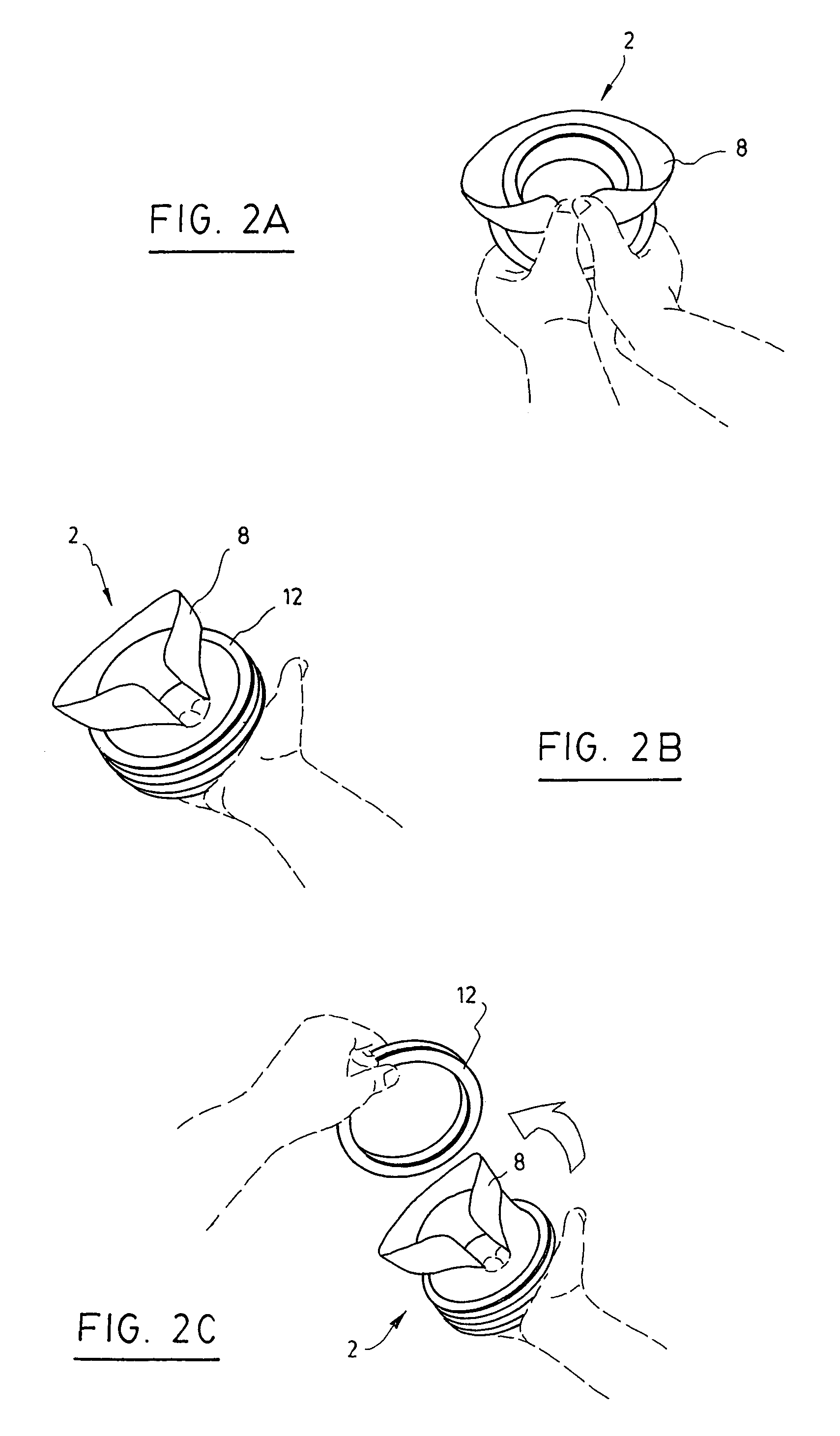
[0018]Referring to FIGS. 1a, 1b, 3 and 4, there is shown a self-fastening tap 2 according to a preferred embodiment of the invention for connecting a branch pipe 20 (shown in FIG. 2e) to an aperture 16 provided in a main pipe 14. Preferably, the main pipe 14 can be a corrugated pipe. The self-fastening tap 2 comprises a hollow cylindrical body 4 having a first open end 3 of a given diameter and a second open end 5 opposed to the first open end 3. The cylindrical body 4 is sized to fit and seal the aperture 16 provided in the main pipe 14. The first open end 3 has an outer side provided with a flexible lip 8 and an inner side provided with an abutment device 10 for abutting the branch pipe 20 so as to prevent the same from being introduced within the cylindrical body 4 beyond the first open end 3. The flexible lip 8 has an outer diameter larger than the diameter of the first open end 3 of the cylindrical body 4. The second open end 5 has an outer side provided with an outer rim 6. Th...


PUM


Abstract

A self-fastening tap for connecting a branch pipe to an aperture of a given diameter provided in a main pipe. The tap comprises a hollow cylindrical body having a first open end of a given diameter and a second open end opposed to the first open end. The cylindrical body is sized to fit and seal the aperture provided in the main pipe. The first open end has an outer side provided with a flexible lip and an inner side provided with abutment means for abutting the branch pipe. The flexible lip has an outer diameter larger than the diameter of the first open end of the cylindrical body. The second open end has an outer side provided with an outer rim. The tap comprises removable at least one spacing ring slideably mounted around the cylindrical body, between the flexible lip and the outer rim.

Description

FIELD OF THE INVENTION[0001]The present invention relates to taps, and more particularly to an easy to install self-fastening tap that can be adjusted with multiple sizes of main pipes for connecting a branch pipe.BACKGROUND[0002]Connecting and joining a branch pipe to a main pipe is generally done by pouring concrete on the joint between the branch pipe and the main pipe. Since the connection between the branch and the main pipes is often underground, it is subjected to breakage due to the weight of the soil above and around the connection, which results in an undesired filtration. Although alternative methods and various mechanical apparatus, such as saddles, are available, they are very costly to implement and must be specially adapted for each situation. For example, a saddle designed to fit around a main pipe can hold the branch pipe and provide a sealed connection between the main and branch pipes. However, using saddles for complex constructions are not usually suitable for c...

Claims


Application Information

Patent Timeline
IPC IPC(8): F16L41/00F16L41/04F16L41/08
CPCF16L41/088
Inventor CHARRETTE, JOSEPH PAULGOYETTE, JEAN CLAUDEVERONNEAU, GERMAIN
Owner PLASTIQUES GYF LTEE (CA)
Learn More