
Coupling Device For Transferring Fluid, Circuit Incorporating and Fitting/Removing It

a fluid transfer and coupling technology, applied in the direction of couplings, pipe elements, sleeve/socket joints, etc., can solve the problems of not always easy operation of assembling these components, the connection is no longer possible subsequently to enter the groove, and the device cost is relatively high, so as to improve the secure connection and ensure the connection. the effect of the connection

Inactive Publication Date: 2010-09-09
HUTCHINSON SA
View PDF12 Cites 18 Cited by
  • Summary
  • Abstract
  • Description
  • Claims
  • Application Information

AI Technical Summary

Benefits of technology

[0013]It will be noted that these tabs that are elastically deformable under flexion forming the coupling end of the locking member according to the invention have the advantage of low cost and ease of fitting of the coupling device by comparison with the known two-component devices and also play a part in conferring mechanical resistance to being pulled out (i.e. to this coupling end up out of the groove of the female end fitting at an inopportune moment) which is enhanced by comparison with that of the aforementioned known devices, thus contributing to the reliability of the coupling even under high operating fluid pressure.
[0040]Advantageously, in order to perform step c), the aforementioned means of making the coupling more secure that the locking member exhibits is / are brought under said radial projection(s) of the male end fitting, preferably by clipping of at least one tongue that forms this means under a corresponding retaining tooth that forms the or each projection.

Problems solved by technology

One major disadvantage of these known coupling devices is that when the male end fitting is locked into the female end fitting when the linking member is not positioned in the coupling groove of the female end fitting, it is no longer subsequently possible to bring the linking member into this groove.
One other disadvantage of these known devices is that they all require two separate components (i.e. a linking member that makes the connection in the groove of the female end fitting and a locking member for locking this linking member), which means that the operation of assembling these components is not always easy and furthermore the cost of the device is relatively high notably because of the use of different materials for these components.

Method used


Image

  • Coupling Device For Transferring Fluid, Circuit Incorporating and Fitting/Removing It
  • Coupling Device For Transferring Fluid, Circuit Incorporating and Fitting/Removing It
  • Coupling Device For Transferring Fluid, Circuit Incorporating and Fitting/Removing It

Examples


Embodiment Construction

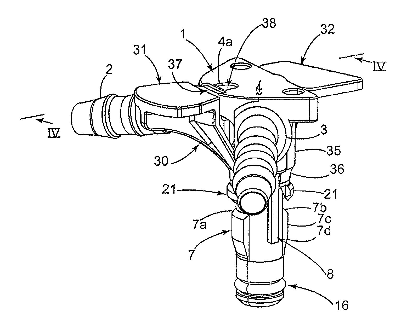
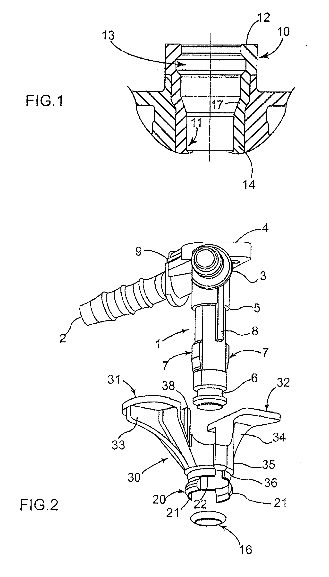
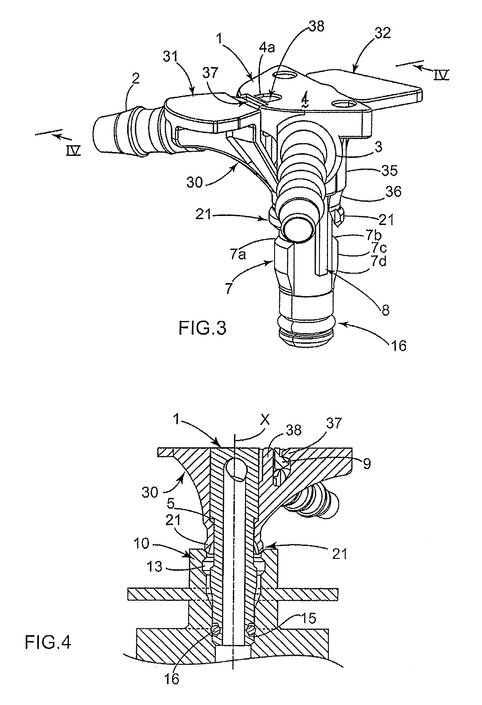
[0050]The male tubular end fitting 1 illustrated notably in FIGS. 2 to 5 has, in the known way, at its axially outer (i.e. upper) end two christmas tree-shaped connection couplings 2 and 3 running symmetrically in relation to one another with respect to a bearing surface 4 for the operator that this end fitting 1 has and which is centered on the axis X thereof (see FIG. 4). The end fitting 1 also has a circumferential radial discontinuity 5 (see FIGS. 2 and 4) to assist with the fitting of the device 1.

[0051]The female tubular end fitting 10 illustrated in FIG. 1, of the canular type and of standard shape, essentially has, on its radially internal face 11, in the immediate vicinity of its axially upper end 12, a circumferential coupling groove 13 which is of substantially trapezoidal axial section and intended to accept an axially inner (i.e. lower in FIG. 2 et seq.) coupling end 20. The female end fitting 10 also has, in the immediate vicinity of its axially inner end 14, a circumf...


PUM

PropertyMeasurementUnit
radius of curvatureaaaaaaaaaa
radial bendingaaaaaaaaaa
internal diameteraaaaaaaaaa

Abstract

Coupling device is provided having a male tubular end fitting; a connection means to be mounted around the male end fitting by being coupled to a female end fitting and comprising a coupling end to be housed in a groove of the female end fitting; and a locking member for locking this connection means that is to be mounted around the male end fitting in order reversibly to bring said coupling end into a locked position in said groove. The connection means comprises a radially internal bearing zone to be mounted against the male end fitting and ending in said coupling end, which comprises tabs that are elastically deformable in the radial direction extending the bearing zone, each tab being able to be jammed in the locking position by flexing against the groove and against one of the guide and locking-aid ramps of the male end fitting.

Description

CROSS REFERENCE TO RELATED APPLICATION[0001]This application claims priority from French application Ser. No. 09 / 01020, filed Mar. 5, 2009, which is hereby incorporated herein in its entirety by reference.BACKGROUND[0002]The present invention relates to a coupling device for a fluid transfer line, to a fuel injector return circuit incorporating it, and to a method for fitting / removing this device around a male tubular end fitting and into / from in a female tubular end fitting that is to be coupled to this male end fitting. The invention applies in general to any couplings between such end fittings that transfer a fluid, particularly at low pressure, and notably to fuel injection line sets for motor vehicles.[0003]In general, it is known practice for fuel injection line sets to use coupling devices involving a male tubular end fitting that is pushed in a leaktight manner into a female tubular end fitting or “canular” by means of a flexible linking member which is mounted securely on t...

Claims


Application Information

Patent Timeline
Patent Type & Authority Applications(United States)
IPC IPC(8): F16L25/00F16L21/08F16L35/00B23P17/04
CPCF02M55/002F02M55/004F02M2200/853Y10T29/49826F16L37/133F16L2201/10F16L37/098
Inventor ULLY, STEPHANEGILLET, DAMIEN
Owner HUTCHINSON SA
Learn More