Drive System for Use with Flowing Fluids

Inactive Publication Date: 2010-09-09
MICU TARFIN
View PDF18 Cites 18 Cited by
  • Summary
  • Abstract
  • Description
  • Claims
  • Application Information

AI Technical Summary

Benefits of technology

[0006]The present invention preferably includes a drive system having a first turbine connected to a shaft, a first gear connected to the shaft, a second turbine rotatably mounted on a pipe, a second gear rotatably mounted on the pipe and connecte

Problems solved by technology

The efficiency of prior art devices that use the wind's kinetic energy to do work is not very high.
Thus, a great deal of energy remains in the wind.
While many drive systems have been tried, each of the prior art systems has a low efficiency when it comes to extracting the wind's energy.

Method used


Image

  • Drive System for Use with Flowing Fluids
  • Drive System for Use with Flowing Fluids
  • Drive System for Use with Flowing Fluids

Examples


Embodiment Construction

[0014]Specific embodiments of the invention will now be described with reference to the figures. Like elements in the various figures will be referenced with like numbers for consistency.

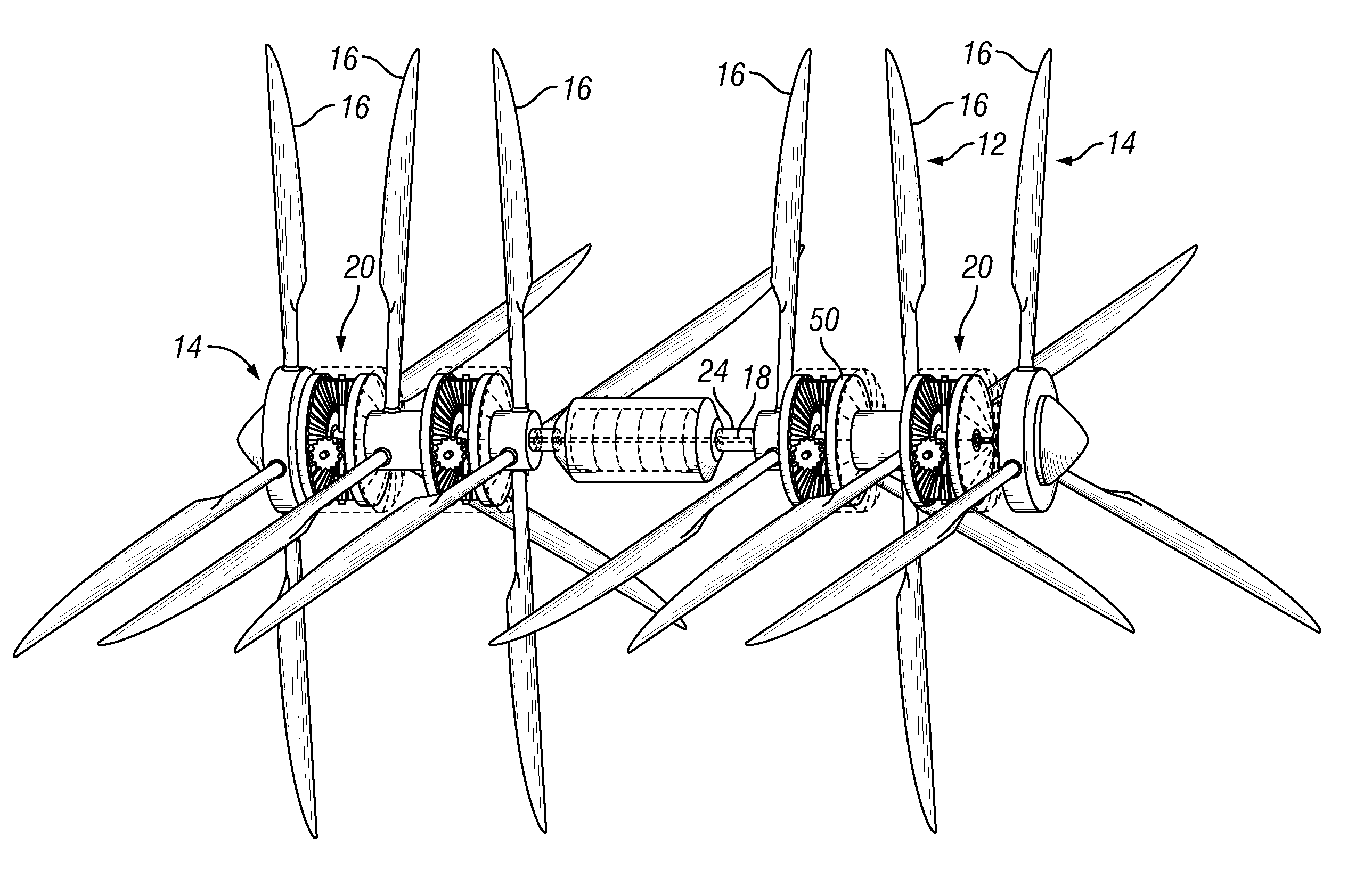
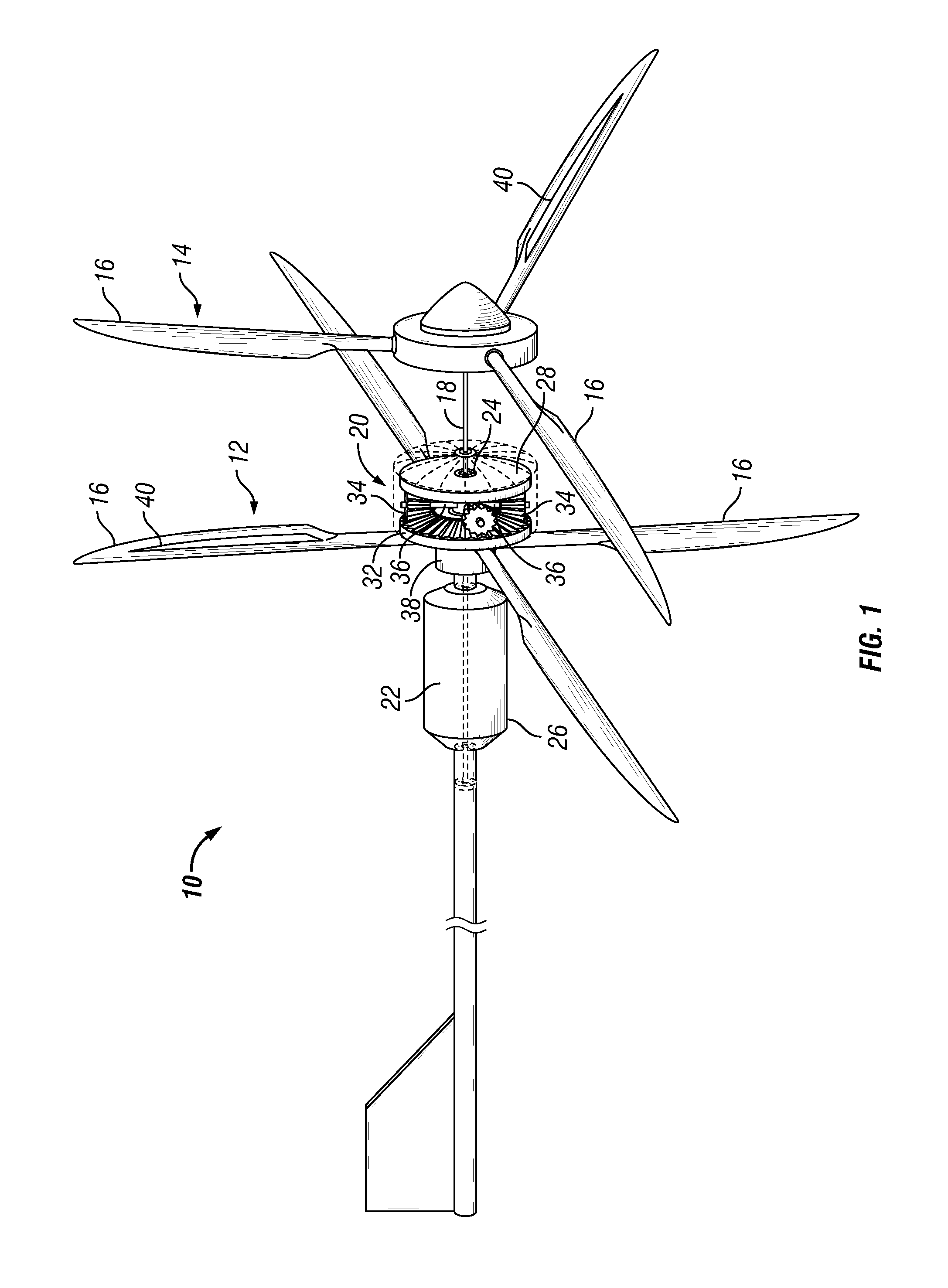
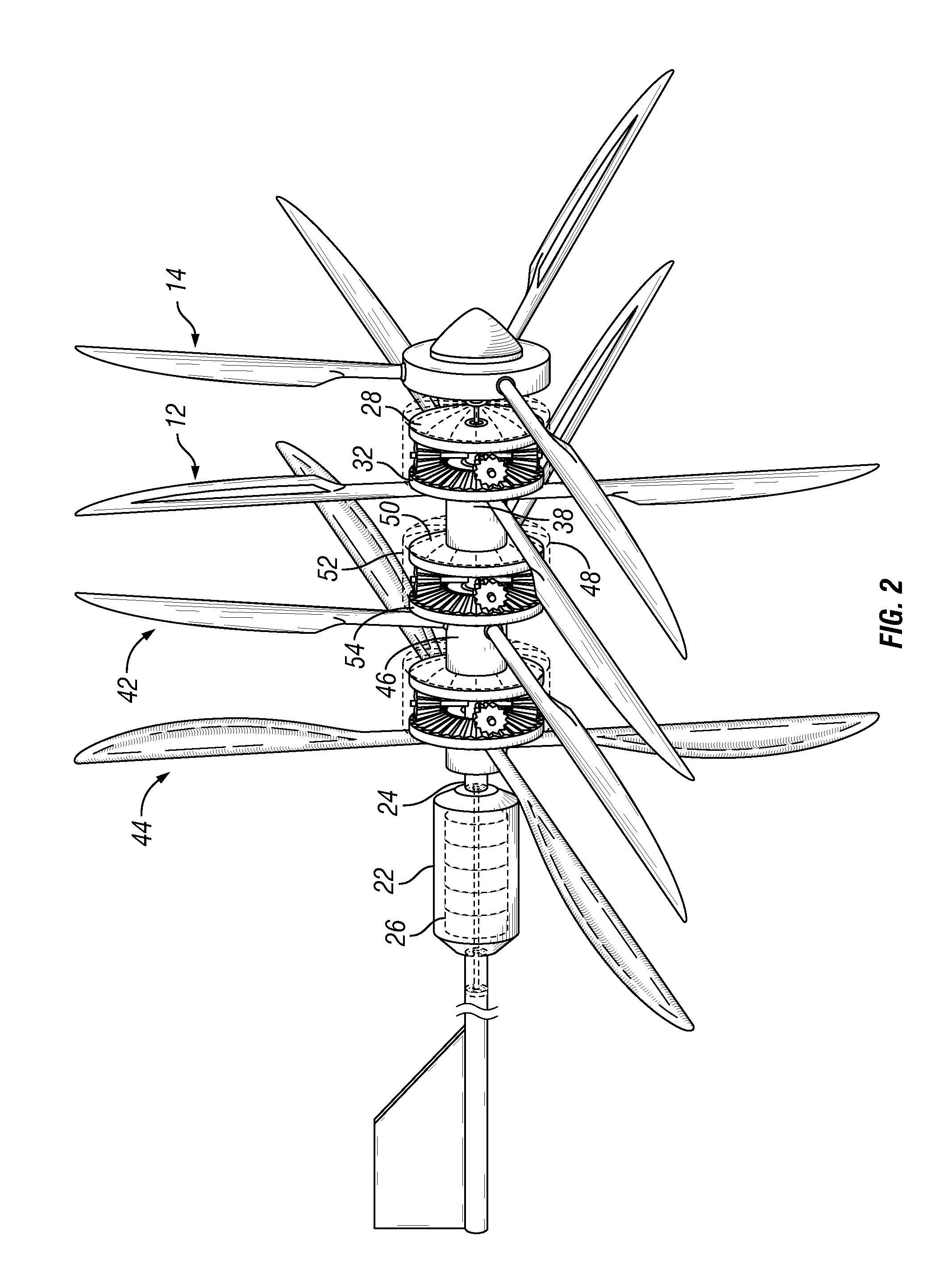
[0015]FIG. 1 shows a wind generator 10 with a first turbine 12 and a second turbine 14. First turbine 12 has four blades 16 in the embodiment shown, though more or fewer blades could be used. Similarly, second turbine 14 has three blades 16 in the embodiment shown, though more or fewer blades could be used. Second turbine 14 is connected to a shaft 18 that extends through a gearbox 20 and into an electrical generator 22. Shaft 18 serves to rotate the rotor of generator 22, as is well known in the art. Shaft 18 is preferably aligned with an axis of symmetry of second turbine 14 so as to be statically and dynamically balanced when rotated.

[0016]Wind generator 10 also has a pipe 24 disposed between first turbine 12 and electrical generator 22. Pipe 24 may be an integral extension of a generator housing...


PUM


Abstract

The present invention includes a drive system for use in a flowing fluid, the drive system preferably having a first turbine connected to a shaft, a first gear connected to the shaft, a second turbine rotatably mounted on a pipe, a second gear rotatably mounted on the pipe and connected to the second turbine, and two or more satellite gears in fixed locations relative to the pipe and rotatably engaged, directly or indirectly, with the first gear and the second gear. The drive system may be used, for example, in a wind generator to generate electrical energy.

Description

BACKGROUND OF INVENTION [0001]1. Field of the Invention[0002]The present invention relates generally to extracting energy from a flowing fluid, and particularly to transferring the kinetic energy of a flowing fluid to a rotatable shaft.[0003]2. Background Art[0004]Devices such as windmills and wind generators have been used for many years to extract energy from the wind and use it to do work. For example, windmills have traditionally been used to pump water or turn a millstone. Wind generators are used to convert the mechanical (i.e., kinetic) energy of the wind to electrical energy. Both windmills and wind generators get their energy from wind blowing onto rotating blades that cause a shaft to rotate. In the applications described above, the rotating shaft is coupled to a mechanical device or an electrical generator.[0005]The efficiency of prior art devices that use the wind's kinetic energy to do work is not very high. For example, in many configurations much of the wind flows pas...

Claims


Application Information

Patent Timeline
IPC IPC(8): F03D9/00F16H57/08
CPCF03D1/025Y02E10/722F05B2260/4031F03D11/02F03D9/25F03D9/28F03D15/00F03D15/10Y02E10/72
Inventor MICU, TARFIN
Owner MICU TARFIN
Why Eureka
Try Eureka