Rear floor structure in vehicle body rear part

a rear floor and rear part technology, applied in the direction of roofs, vehicle arrangements, transportation and packaging, etc., can solve the problems of difficult adjustment, increased floor height of cargo compartment in the vehicle body rear part, and difficulty in use of cargo compartments

Active Publication Date: 2010-09-09
SUZUKI MOTOR CORP
View PDF6 Cites 29 Cited by
  • Summary
  • Abstract
  • Description
  • Claims
  • Application Information

AI Technical Summary

Benefits of technology

[0022]Moreover, in the case in which the joint of the back panel and the spare tire placing panel and the joint of the spare tire bracket and the spare tire placing panel are accomplished by bolt fastening, at the time of manufacturing, the welding work for welding the back panel to the rear floor and the sealer applying work can be performed easily.
[0023]Also, in the present invention, the back panel is formed into a curved shape projecting toward the vehicle rea

Problems solved by technology

Unfortunately, for the above-described conventional storage structure, since the inclined surface 52 on which the rear part 53a of the spare tire 53 is placed is formed on the rear floor 51, it is difficult to make adjustments so as to prevent the spare tire 53 from being displaced to the vehicle front when an impact load is applied from the vehicle rear.
That is to say, the conventional storage structure has

Method used


Image

  • Rear floor structure in vehicle body rear part
  • Rear floor structure in vehicle body rear part
  • Rear floor structure in vehicle body rear part

Examples


Embodiment Construction

[0030]The present invention will now be described in detail based on embodiments shown in the drawings.

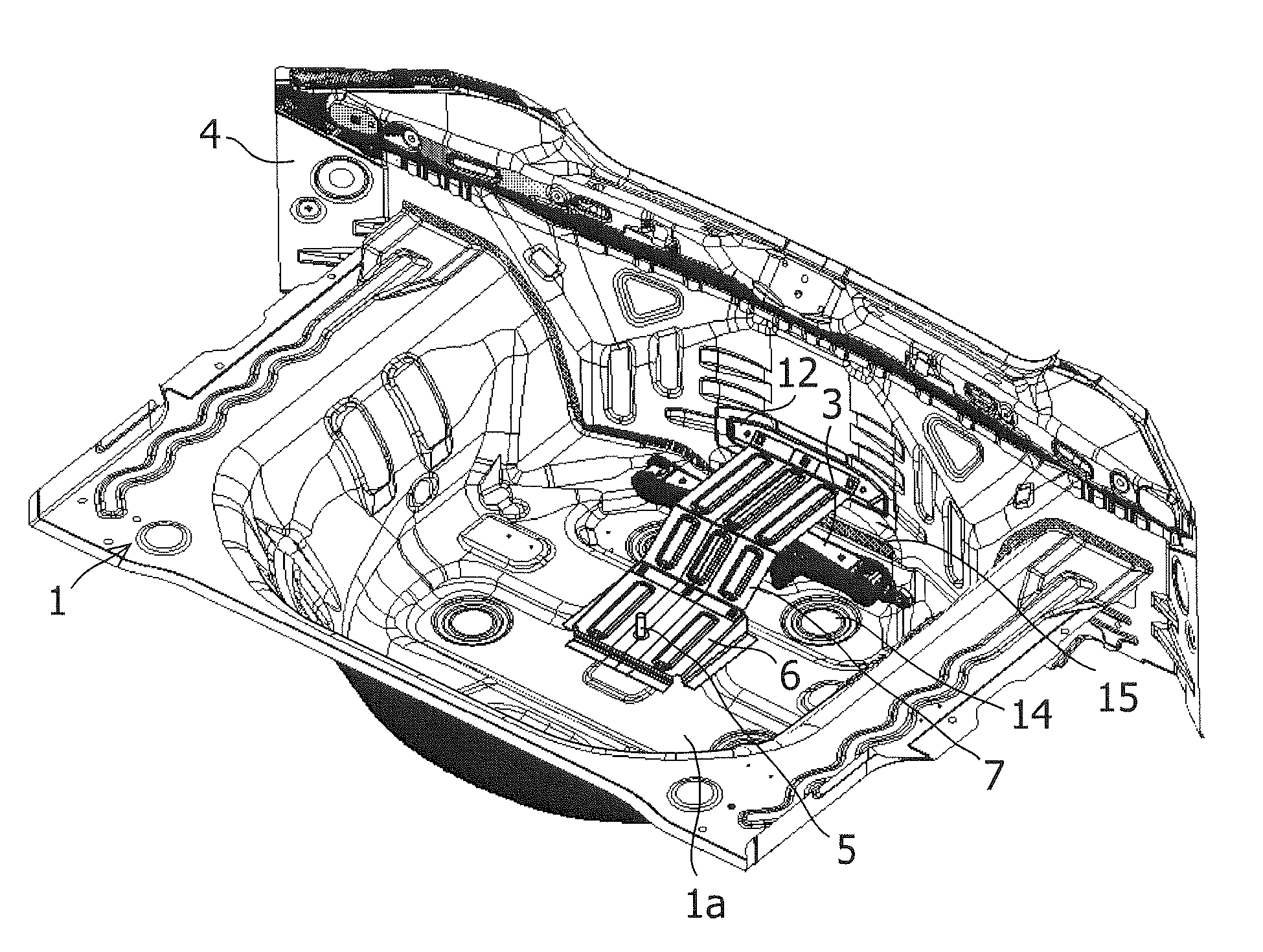
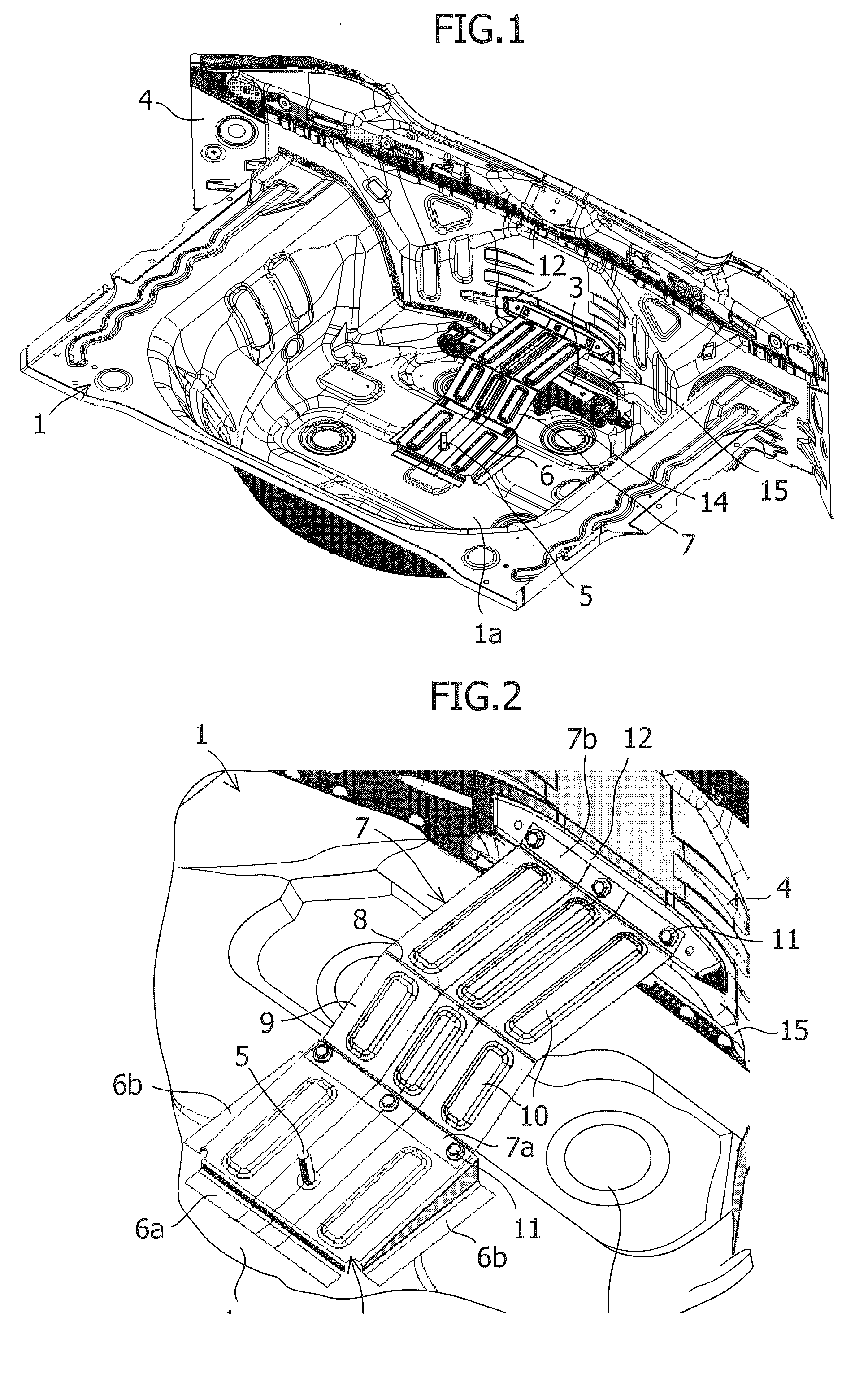
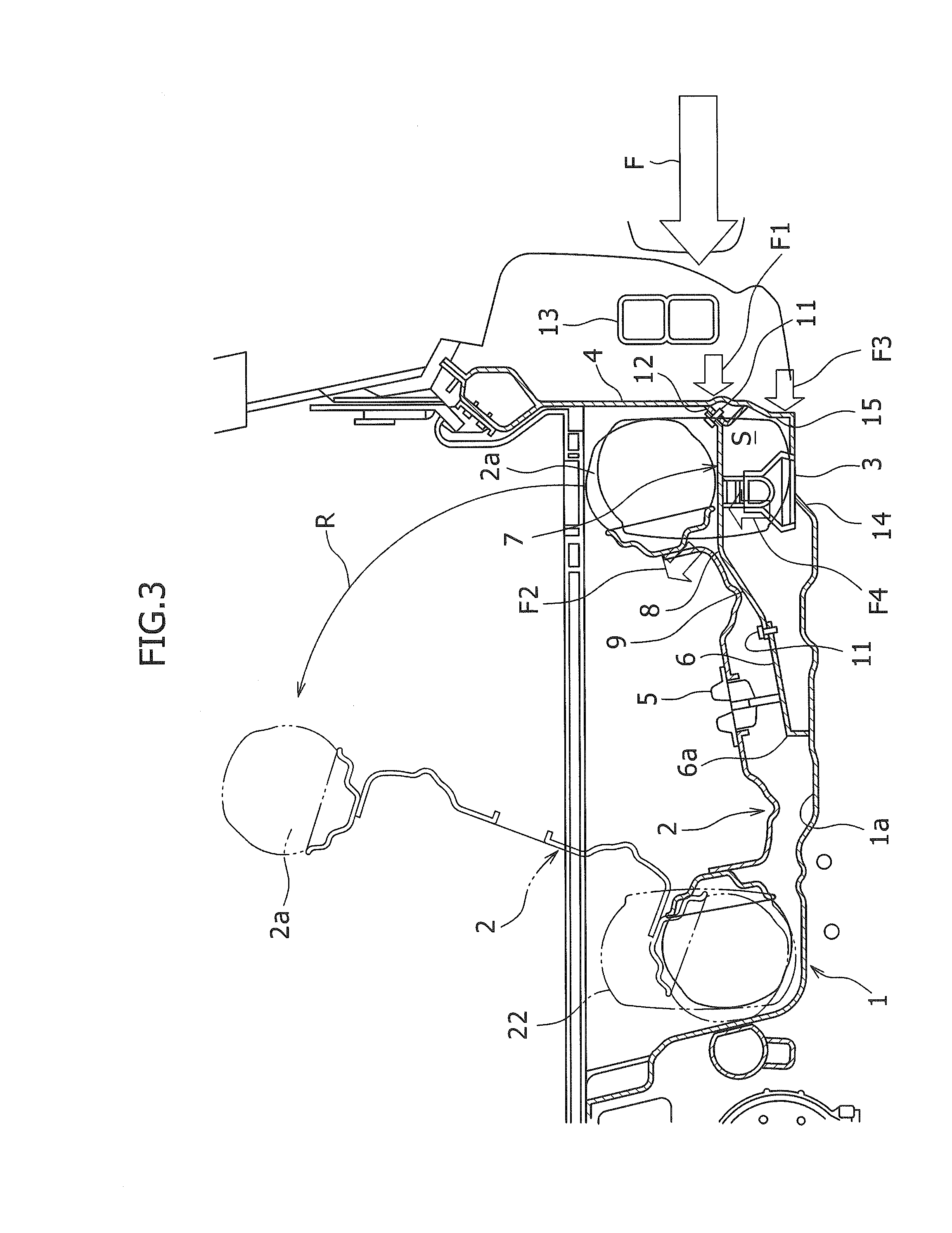
[0031]FIGS. 1 to 4 show a rear floor structure in a vehicle body rear part in accordance with an embodiment of the present invention.

[0032]As shown in FIGS. 1 to 4, on a rear floor 1 in the vehicle body rear part of an automobile in accordance with the embodiment of the present invention, a concave-shaped tire storage part 1a depressed downward is formed, and in this tire storage part 1a, a horizontally disposed spare tire 2, a jack 3, which is a rigid member, and the like are stored. In the rear end part of the rear floor 1, a back panel 4 extending along with the vehicle width direction is erectingly provided.

[0033]Above the bottom surface of the tire storage part 1a, a spare tire bracket 6 having a spare tire fixture 5 for tightening the spare tire 2 by being inserted through the hole in the spare tire 2 and a spare tire placing panel 7 on which the rear part of the spare tire 2...


PUM


Abstract

A rear floor structure in a vehicle body rear part has a spare tire placing panel having an inclined surface inclined downward toward the vehicle front provided above a rear floor, and a spare tire tiltingly mounted on the spare tire placing panel. In the rear floor structure, in an intermediate portion in the front and rear direction of the spare tire placing panel, a convex part directed upward is provided so as to extend along the vehicle width direction; between the rear floor and the spare tire placing panel in the vertical direction, a space for disposing a jack, being a rigid member, is formed; and on the vehicle front side of the axis center of the jack on the rear floor, a projecting part extending in the vehicle width direction is provided.

Description

CROSS-REFERENCE TO RELATED APPLICATIONS[0001]This application claims the benefit of the filing date of Japanese Patent Application No. 2009-051753 filed Mar. 5, 2009, the entire disclosure of which is hereby incorporated herein by reference.FIELD OF THE INVENTION[0002]The present invention relates to a rear floor structure in the vehicle body rear part of an automobile.BACKGROUND OF THE INVENTION[0003]In the vehicle body rear part of an automobile, a storage part for storing a horizontally disposed spare tire is provided. For example, in the spare tire storage structure disclosed in Patent Document 1 (JP 62-102783 U), as shown in FIG. 6, an inclined surface 52 is formed in the rear part of a rear floor 51, and a spare tire 53 is stored in such a manner that a rear part 53a thereof is placed on the inclined surface 52. A front part 53b of the spare tire 53 is fixed by pressing a fixture 54, which is attached to the rear floor 51, from above.[0004]In such a spare tire storage structur...

Claims


Application Information

Patent Timeline
IPC IPC(8): B62D43/06
CPCB62D43/10B62D21/152
Inventor TANEDA, KODAI
Owner SUZUKI MOTOR CORP
Why Eureka
Try Eureka