Power management system and method of operating the same

Active Publication Date: 2010-09-09
BRIGGS & STRATTON LLC
View PDF37 Cites 72 Cited by
  • Summary
  • Abstract
  • Description
  • Claims
  • Application Information

AI Technical Summary

Benefits of technology

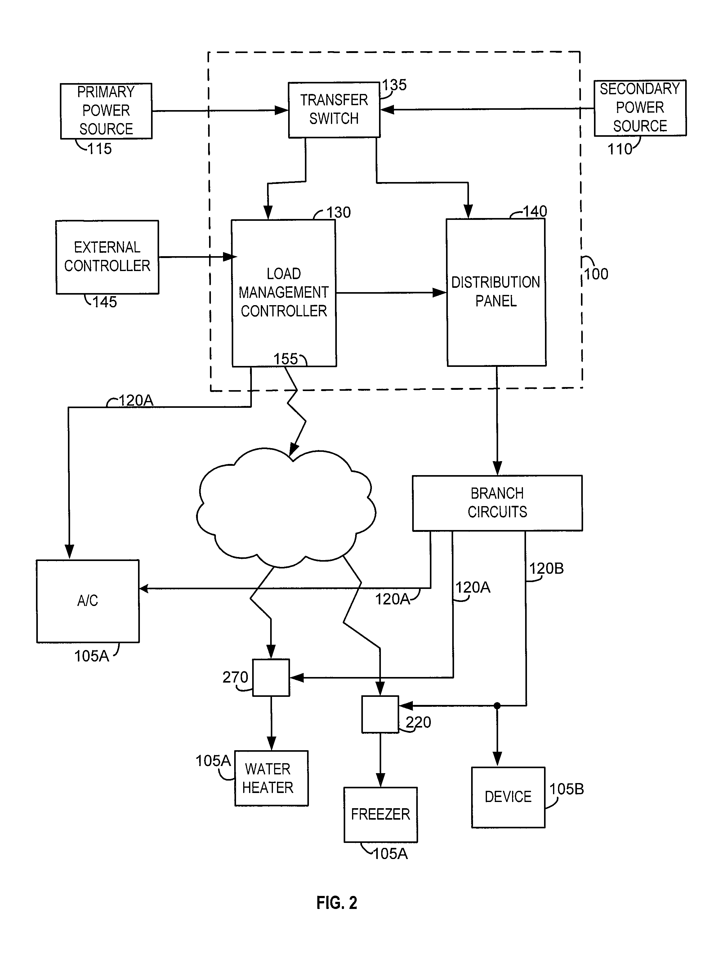
[0006]The system includes a portable receptacle electrically connected in circuit between the electrical outlet and a second managed device. The portable receptacle is, by definition, portable, and allows a user to vary the second managed device without re-wiring the system. The portable receptacle includes a first antenna, a switch to electrically connect the electrical outlet to the second managed device, and circuitry electrically connecting the first antenna and the switch. The circuitry includes a first controller to control the switch based on a s

Problems solved by technology

In general, as the amount of rated power (or current) increases, the size, weight, and cost of the generator increases, and the amount of noise produced by the

Method used


Image

  • Power management system and method of operating the same
  • Power management system and method of operating the same
  • Power management system and method of operating the same

Examples


Embodiment Construction

[0016]Before any embodiments of the invention are explained, it is to be understood that the invention is not limited in its application to the details of construction and the arrangements of components set forth in the following description or illustrated in the following drawings. The invention is capable of other embodiments and of being practiced or of being carried out in various ways. Also, it is to be understood that the phraseology and terminology used herein is for the purpose of description and should not be regarded as limiting. The use of “including,”“comprising,” or “having” and variations thereof is meant to encompass the items listed thereafter and equivalence thereof as well as additional items. The terms “connected,”“coupled,” and “mounted” and variations thereof is meant to encompass direct and indirect connections, couplings, and mountings. In addition, the terms “connected” and “coupled” and variations thereof are not restricted to physical or mechanical connecti...


PUM


Abstract

A power management system connectable to a primary power source and a secondary power source, and a method of operating the power management system. A transfer switch is electrically connected to the primary and secondary power sources, and a plurality of branch circuits are electrically connected to the transfer switch. The plurality of branch circuits includes a plurality of electrical outlets. The system includes a controller wirelessly coupled to a plurality of portable receptacles, which are coupled between respective electrical outlets and managed devices. The controller manages the receptacles, and consequently the managed devices, during the second power source powering the transfer switch.

Description

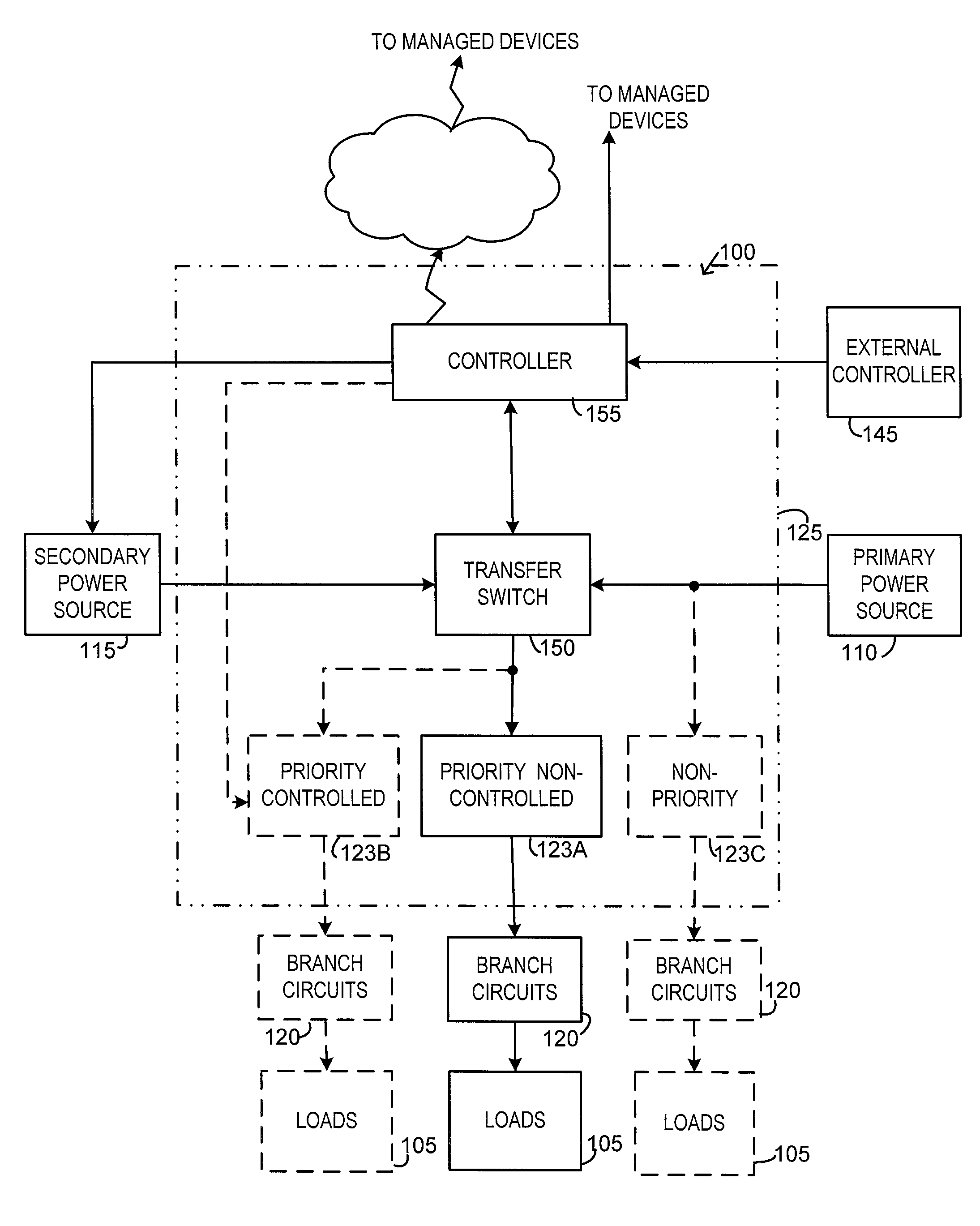
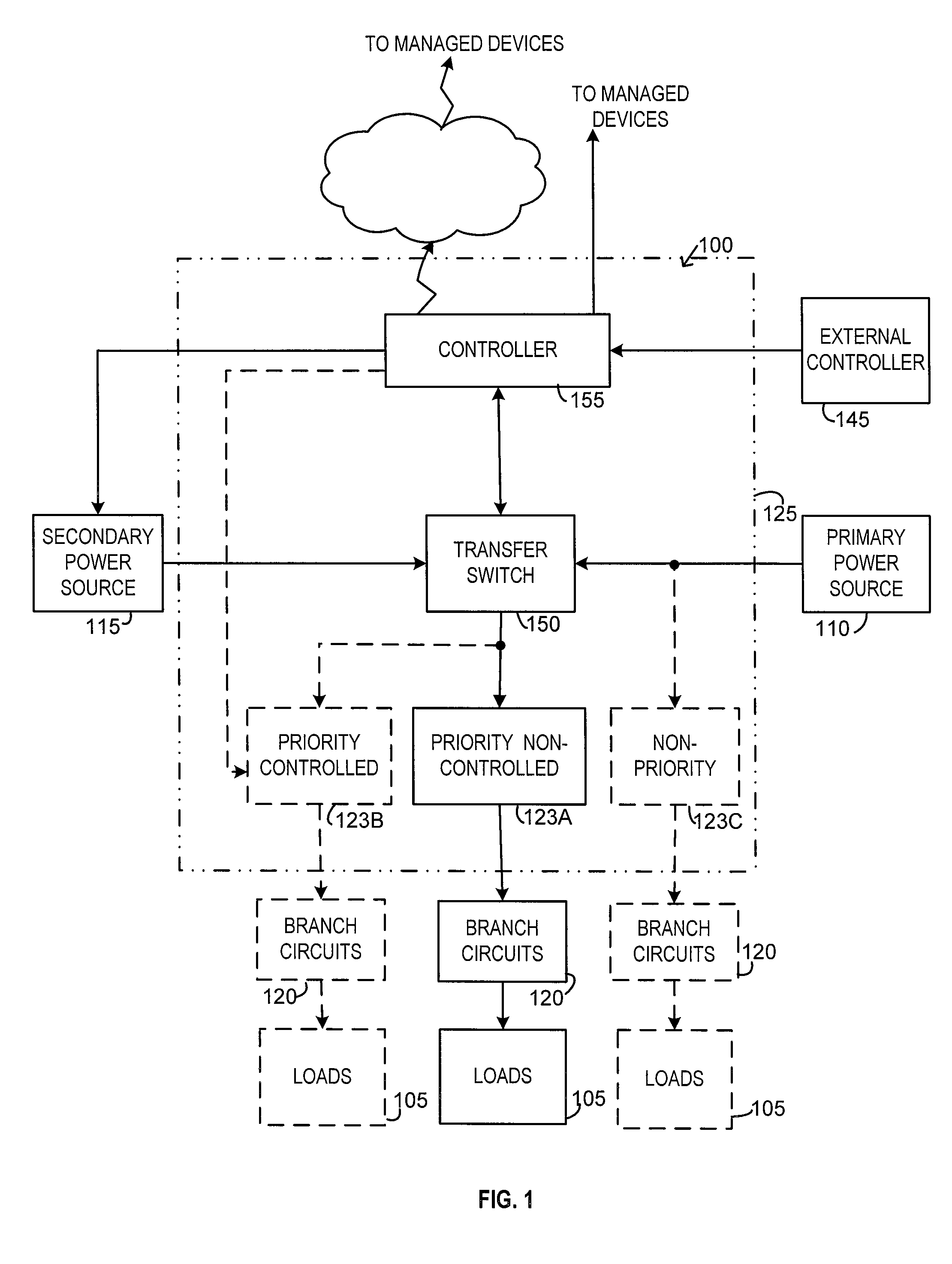
BACKGROUND OF THE INVENTION[0001]The invention relates to power management systems and methods of operating power management systems.[0002]Typical power transfer systems connect one or more circuit branches to either a primary power source, such as utility power, or a secondary power source, such as a portable or standby generator. Each circuit branch can connect to one or more loads, and typically includes one or more manually controlled circuit breakers that are controllable by an operator.[0003]For typical power transfer systems located at a residence, the systems connect a plurality of circuits to a generator acting as the secondary power source. Residential generators vary in size and power output. In general, as the amount of rated power (or current) increases, the size, weight, and cost of the generator increases, and the amount of noise produced by the engine, which powers the generator, increases. Therefore, it is beneficial to use a power management system for controlling ...

Claims


Application Information

Patent Timeline
IPC IPC(8): H02J3/14
CPCH02J3/14H02J9/06H02J13/0075Y02B70/3225Y02B70/3291Y04S40/126Y04S20/12Y04S20/222Y04S20/248Y02B90/2653Y02B90/222H02J13/00034Y02B70/30Y02B90/20H02J13/00022
Inventor STAIR, KENNY J.BATZLER, BRANDON MICHAEL
Owner BRIGGS & STRATTON LLC
Why Eureka
Try Eureka