Holder for a position sensor

a position sensor and holder technology, applied in the field of holder for a position sensor, can solve the problems of reducing the resilience of the spring and permanent set, and achieve the effects of accurate alignment, and accurate alignment relative to the rotor

Inactive Publication Date: 2010-09-09
DYSON TECH LTD
View PDF7 Cites 1 Cited by
  • Summary
  • Abstract
  • Description
  • Claims
  • Application Information

AI Technical Summary

Benefits of technology

[0018]Preferably, the abutment is biased against a pole of the stator. Accordingly, the position sensor may be accurately aligned with respect to a pole of the stator. A rotor of the electric machine rotates relative to the poles of the stator. By accurately aligning the position sensor relative to a pole of the stator, accurate alignment relative to the rotor may also be achieved.
[0019]More preferably, the abutment comprises a wall having a ridge, and the wall abuts a side of a pole of the stator and the ridge abuts a face of the pole. Accordingly, the position sensor is accurately positioned relative to a slot opening in the stator. The position sensor typically senses the position of a rotor of the electric machine via the slot opening. By accurately aligning the position sensor relative to a slot opening in the stator, accurate alignment relative to the rotor may also be achieved. Indeed, the wall of the abutment advantageously comprises a pair of ridges, and the biasing mechanism biases the ridges within the slot opening. Accordingly, regardless of the direction along the x-axis in which the biasing mechanism biases the abutment, a ridge is nevertheless biased against the face of a pole. The ridges are ideally separated by a distance substantially corresponding to the width of the slot opening. Accordingly, movement of the abutment along the x axis is tightly controlled.
[0020]The biasing mechanism may be mounted to a housing of the electric machine. Moreover, the housing may comprise a pair of posts to which the biasing mechanism is mounted. The stator may also be mounted to the same posts (e.g. the stator may include recesses into which the posts are received). Since the stator and sensor holder and mounted to the same fixture, namely the posts, geometric tolerances associated with the alignment of the sensor holder and stator are reduced. The electric machine may also comprise a printed circuit board that overlies the stator and sensor holder and is screwed to the posts of the housing so as to secure the stator, sensor holder and printed circuit board to the housing. This particular arrangement then has the advantage of providing a compact design of electric machine.
[0021]The position sensor is preferably a Hall-effect sensor. Accordingly, a relatively cheap solution is provided for sensing the position of a permanent-magnet rotor.
[0022]The electric machine may be relatively small and comprise a rotor having a diameter of no more than 50 mm. The electric machine is therefore compact but is nevertheless capable of relatively good efficiency by virtue of the sensor holder, which ensures that the position sensor is accurately aligned relative to the rotor.

Problems solved by technology

Any stretching of the arcuate arms reduces the resilience of the springs and ultimately leads to permanent set.

Method used


Image

  • Holder for a position sensor
  • Holder for a position sensor
  • Holder for a position sensor

Examples


Embodiment Construction

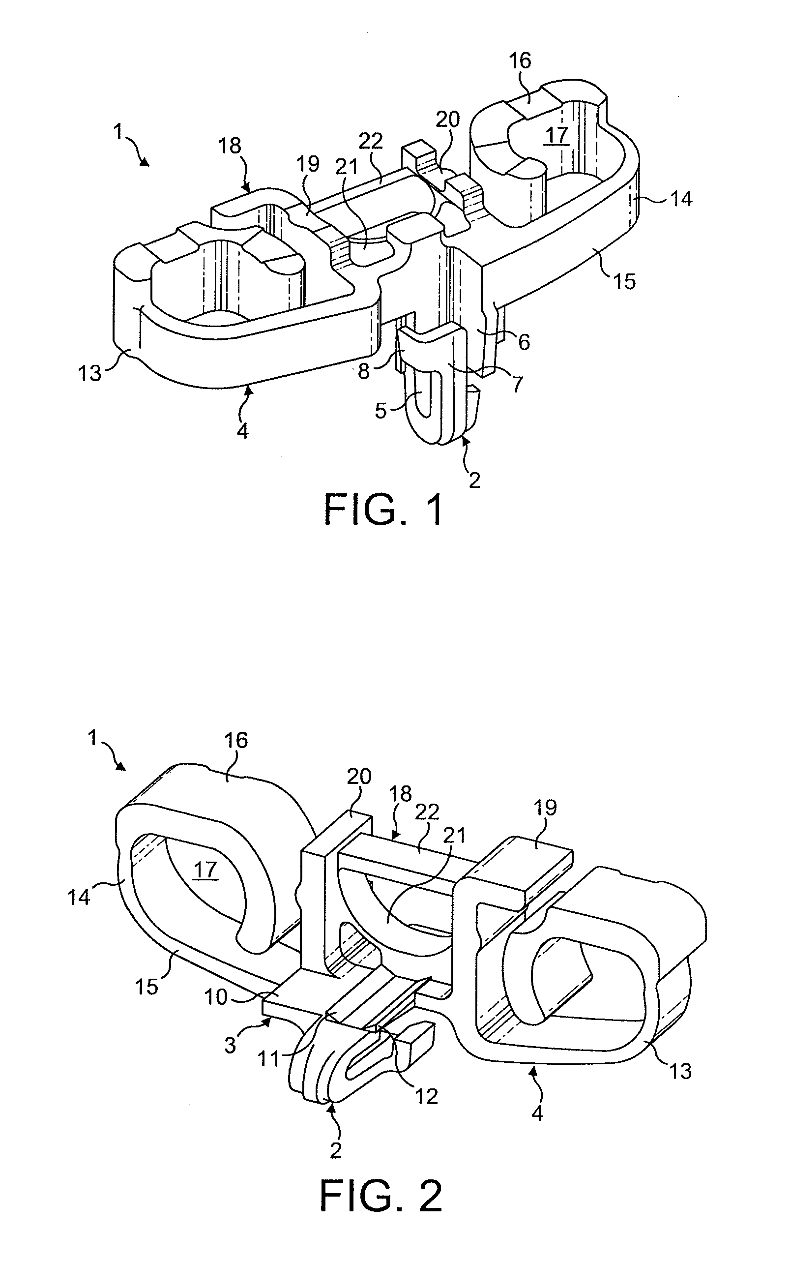
[0029]The sensor holder 1 of FIG. 1 comprises a pocket 2, an abutment 3 and a biasing mechanism 4.

[0030]The pocket 2 defines a recess into which a position sensor may be held. The pocket 2 comprises a front wall 5 connected to a first side wall 6, and a rear wall 7 connected to a second side wall 8. The rear wall 7 is resiliently connected to the front wall 5 at a base. The rear and second side walls 6,7 are thus able to move resiliently relative to the front and first side walls 5,6. In having a pair of resilient walls 6,7, a position sensor is held tightly within the pocket 2. Moreover, the position sensor is held firmly against the front wall 5 of the pocket. Consequently, not only the position but also the orientation of the position sensor is aligned within the pocket 5.

[0031]The abutment 3 comprises a wall 10 having a planar outer surface on which a pair of ridges 11,12 is formed. The wall 10 of the abutment 2 forms part of the pocket 2. In particular, the wall 10 forms part o...


PUM


Abstract

A holder for a position sensor of an electric machine. The holder includes a pocket for holding the position sensor, an abutment, and a biasing mechanism mountable to a fixture of the electric machine so as to bias the abutment relative to the fixture. Additionally, an electric machine that incorporates the holder, the electric machine including a stator against which the biasing mechanism biases the abutment.

Description

REFERENCE TO RELATED APPLICATIONS[0001]This application claims the priority of United Kingdom Application No. 0903586.6, filed Mar. 3, 2009, the entire contents of which are incorporated herein by reference.FIELD OF THE INVENTION[0002]The present invention relates to a holder for a position sensor of an electric machine, and to an electric machine incorporating the same.BACKGROUND OF THE INVENTION[0003]The output power of an electric machine is critically dependant on accurate synchronisation of phase energisation and rotor position. The electric machine therefore requires mechanism for accurately determining the position of the rotor. A relatively cheap solution is a Hall-effect sensor.[0004]Following manufacture and assembly of the electric machine, there is a tolerance in the position of the sensor relative to the stator and rotor. This tolerance in position results in an offset in the electrical angle of the signal output by the sensor. As a result, phase energisation and rotor ...

Claims


Application Information

Patent Timeline
Patent Type & Authority Applications(United States)
IPC IPC(8): H02K11/00
CPCG01D11/30H02K29/10H02K29/08H02K21/185H02K11/215H02K11/22G01D11/24
Inventor GREEN, ROBERT ANDREWSPENCE, NICHOLAS TIMOTHYCHEN, YUCELIK, TUNCAY
Owner DYSON TECH LTD
Why Eureka
Try Eureka