Voltage-measuring circuit and method

a voltage measurement and circuit technology, applied in the field of voltage measurement circuit and method, can solve the problems of difficult and expensive manufacturing of resistive dividers that achieve accurate ratios between large and small resistance values, and the inability to provide very large resistors in integrated circuits

Active Publication Date: 2010-09-09
ANALOG DEVICES INC
View PDF3 Cites 37 Cited by
  • Summary
  • Abstract
  • Description
  • Claims
  • Application Information

AI Technical Summary

Problems solved by technology

In one common scenario, a voltage to be monitored is a relatively high voltage, and the monitoring is performed using a circuit that either cannot operationally monitor a voltage of such a magnitude or which is not desirable to be designed to operate in such a manner as to directly monitor a voltage of such a magnitude.
For example, direct monitoring of a voltage magnitude of several hundred volts may be desired, but such could destroy many integrated circuits that typically can withstand voltage magnitudes of no greater than tens of volts.
A major problem exists, however, with the embodiments of b...

Method used


Image

  • Voltage-measuring circuit and method
  • Voltage-measuring circuit and method
  • Voltage-measuring circuit and method

Examples


Embodiment Construction

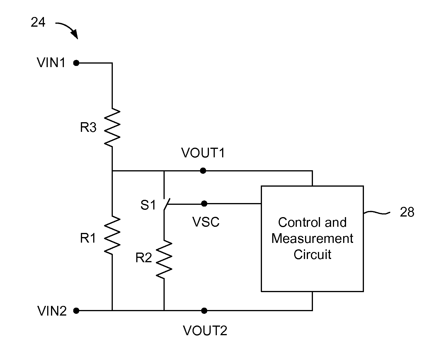
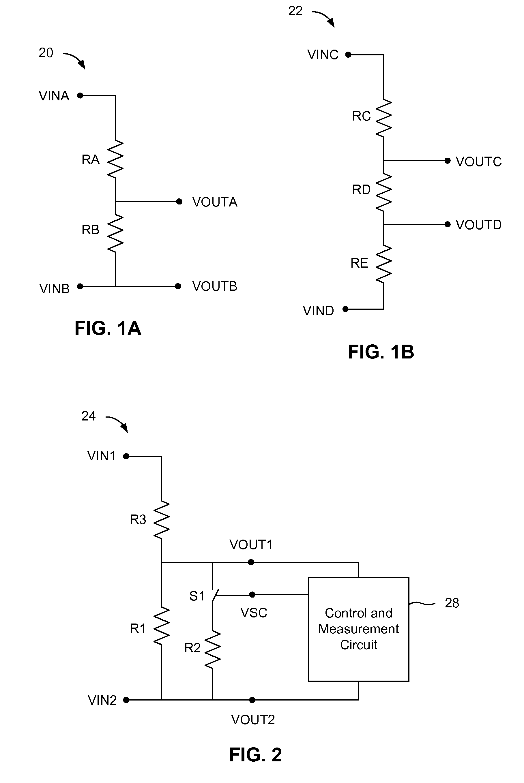
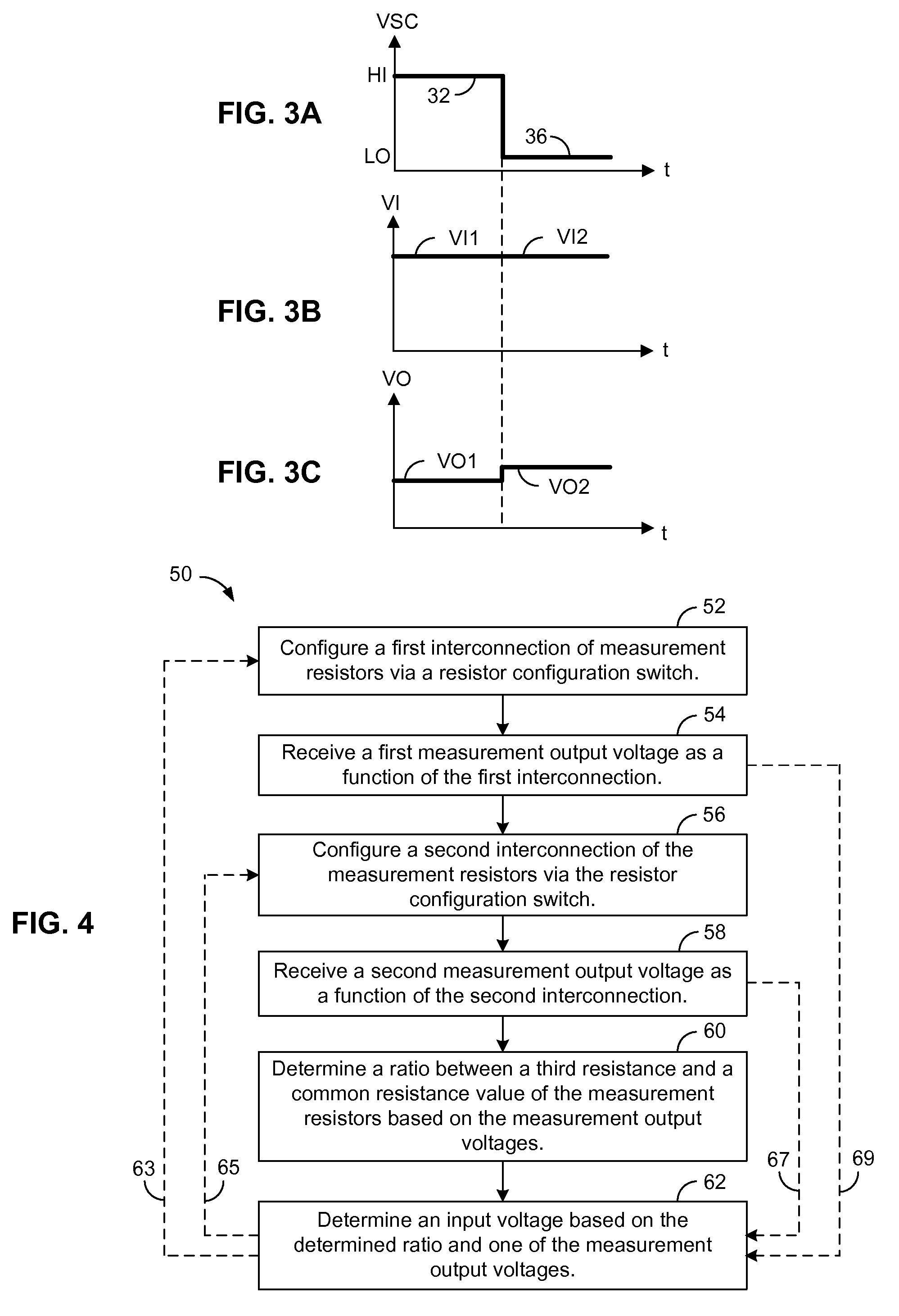
[0023]An embodiment of a voltage measuring circuit include first and second resistors, a configuration switch, and a control and measurement circuit. The first resistor is connected to a first measurement node. The second resistor is connected to the first resistor and a second measurement node. The configuration switch is configured to, in response to a control signal, selectively interconnect the first and second resistors into and out of one of either a parallel or series configuration during two distinct phases (i.e., enable and disable phases) of the control signal, respectively. The control and measurement circuit is configured to provide the control signal, receive a first measurement voltage between the first and second measurement nodes during a first phase (i.e., the enable phase), and receive a second measurement voltage between the first and second measurement nodes during a second phase (i.e., the disable phase).

[0024]An embodiment of a method includes: providing the fi...


PUM


Abstract

An embodiment of a voltage-measuring circuit includes: a first resistor connected to a first measurement node; a second resistor connected to the first resistor and a second measurement node; a configuration switch configured to, in response to a control signal, selectively interconnect the first and second resistors, during enable and disable phases of the control signal respectively, into and out of either a parallel or a series configuration; and a control and measurement circuit configured to provide the control signal, receive a first measurement voltage from the first and second measurement nodes during the enable phase, and receive a second measurement voltage from the first and second measurement nodes during the disable phase.

Description

BACKGROUND INFORMATION[0001]A need exists to measure and monitor voltages in many circuits and applications. For example, a circuit may monitor a supply or signal voltage level to determine specific operating conditions, such as may trigger a shutdown during low-power conditions or a specific circuit operation in response to a predetermined signal level. In one common scenario, a voltage to be monitored is a relatively high voltage, and the monitoring is performed using a circuit that either cannot operationally monitor a voltage of such a magnitude or which is not desirable to be designed to operate in such a manner as to directly monitor a voltage of such a magnitude. For example, direct monitoring of a voltage magnitude of several hundred volts may be desired, but such could destroy many integrated circuits that typically can withstand voltage magnitudes of no greater than tens of volts.[0002]FIGS. 1A and 1B depict typical embodiments of resistive voltage-divider circuits 20, 22 ...

Claims


Application Information

Patent Timeline
IPC IPC(8): G01R1/20
CPCG01R19/0084G01R15/04
Inventor WYNNE, JOHN
Owner ANALOG DEVICES INC
Why Eureka
Try Eureka