Apparatus and Method for Homogenizing Two or More Fluids of Different Densities

a technology of apparatus, applied in the field of apparatus and method for homogenizing two or more fluids of different densities, can solve the problems of increasing the amount of shearing of mixed fluids, dissipating turbulent flow in each line, etc., and achieves the effect of improving the ability to facilitating and improving the ability to rapidly homogenize two or more fluids

Active Publication Date: 2010-09-09
MI
View PDF8 Cites 12 Cited by
  • Summary
  • Abstract
  • Description
  • Claims
  • Application Information

AI Technical Summary

Benefits of technology

[0006]This invention pertains to both an apparatus and a methodology of using that apparatus. The combination of the apparatus and the method work conjointly to improve the homogenization of two or more fluids of different densities and rheological properties through the creation of turbulent flow, shearing and turbulent kinetic energy. The design of the apparatus facilitates and improves the ability to homogenize two or more fluids rapidly while in flow without moving parts or additional energy sources.
[0010]The combined flow continues to the secondary mixing area, wherein there may be two static mixers in series, having shaped orifices offset from each other in the plane of the combined flow. Upon exiting the second static mixer, large eddy currents provide enhanced mixing, shearing and transfer of turbulent kinetic energy for effective homogenization.

Problems solved by technology

However, the turbulent flow in each line dissipates before the mixing area is reached.
In addition, increasing the areas of turbulence would increase the amount of shearing of the mixed fluid.

Method used


Image

  • Apparatus and Method for Homogenizing Two or More Fluids of Different Densities
  • Apparatus and Method for Homogenizing Two or More Fluids of Different Densities
  • Apparatus and Method for Homogenizing Two or More Fluids of Different Densities

Examples


example

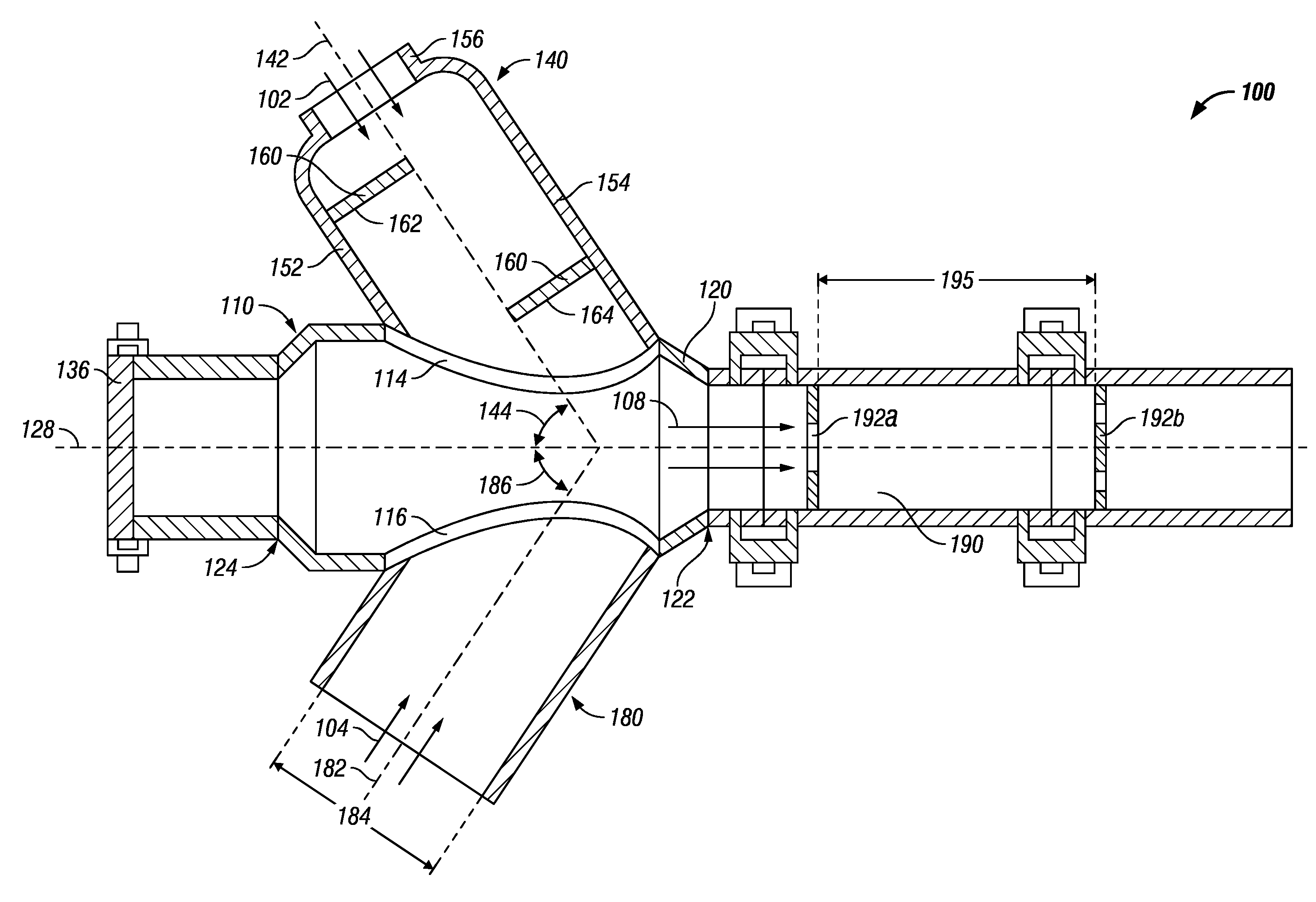
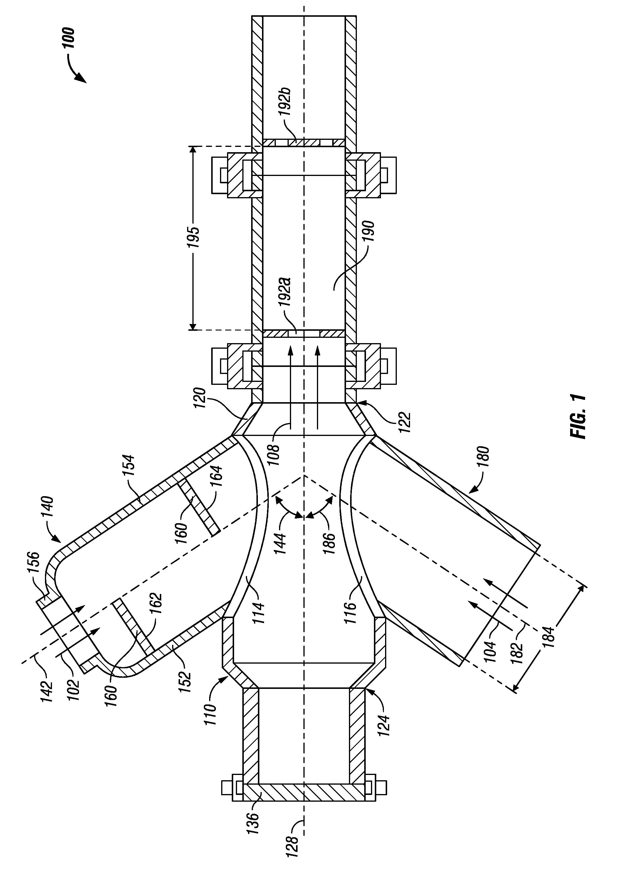
[0049]The homogenization of a barite and bentonite fluid and a brine fluid was modeled through the inline blending apparatus 100 as described. FIGS. 9 and 10 depict different views of the blending contours of the two fluids.

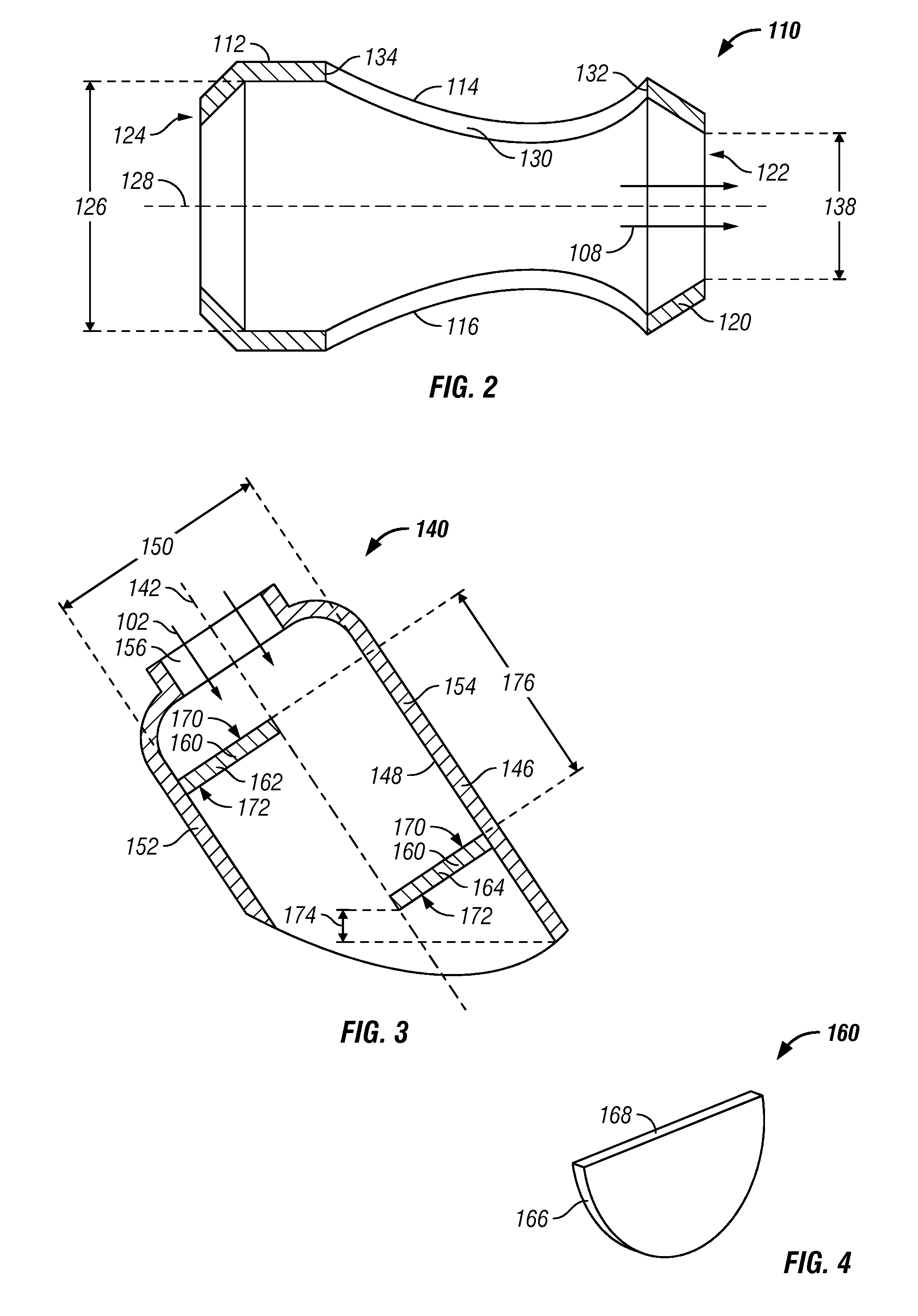
[0050]The barite-bentonite fluid has a higher density than the brine fluid, and is thus introduced through the first fluid director 140. The upstream baffle 162 has a semicircular profile with a surface area that is half of the cross-sectional area of the first fluid director 140. The upstream baffle 162 is affixed to the rearward wall portion 152 of the first fluid director 140 such that the upstream surface 170 is perpendicular to the direction of flow. The upstream baffle 162 induces turbulence to the barite-bentonite fluid stream 200 and directs it toward the downstream baffle 164.

[0051]The downstream baffle 164 is affixed to the forward wall portion 154 of the first fluid director 140 such that the upstream surface 170 is perpendicular to the inner surface 1...


PUM

PropertyMeasurementUnit
offset angleaaaaaaaaaa
densityaaaaaaaaaa
areaaaaaaaaaaa

Abstract

An apparatus for blending two or more fluid streams, wherein a first fluid has a higher density than the other fluids, includes a first fluid director and at least a second fluid director providing fluid communication of a first and second fluid stream, respectively, to a primary mixing chamber. The first fluid director includes one or more baffles to disturb the first fluid stream and to direct it toward a rearward portion of the first inlet to the primary mixing chamber. A secondary blending chamber is in fluid communication with the primary chamber outlet and includes at least one, and preferably two static mixers. When two static mixers are serially retained in the secondary blending chamber, they may be skewed rotationally relative to each other such that the orifice profiles of each static mixer are not in alignment.

Description

[0001]This application claims the benefit of U.S. Provisional Application No. 60 / 609,156, filed Sep. 10, 2004 the contents of which are incorporated herein by reference.BACKGROUND OF INVENTION[0002]When preparing certain types of fluid mixtures, it is sometimes necessary to homogenize two or more fluids having different densities and different rheological properties. It is desired, in some circumstances, that the two or more fluids are blended as they continue to flow downstream.[0003]Traditionally, inline mixing of two or more fluids of different densities requires commingling the fluids, under pressure, in an enclosed space of varying cross-sectional diameter from the inlet lines to the outlet line. The varying cross-sectional diameter creates zones of turbulence and re-circulation, which promotes mixing.[0004]One such prior art method utilizes a series of nozzles through the input lines to create turbulent flow in each of the streams prior to reaching the mixing area. The joined ...

Claims


Application Information

Patent Timeline
Patent Type & Authority Applications(United States)
IPC IPC(8): B01F15/02
CPCB01F2003/105B01F3/0865B01F5/0618B01F5/0256B01F2005/0022B01F23/451B01F23/471B01F2025/915B01F25/23B01F25/4316B01F25/43161
Inventor KAPILA, MUKESHLOMOND, PERRY
Owner MI
Why Eureka
Try Eureka