Communication System, Node, Terminal and Communication Method and Program

a communication system and terminal technology, applied in the field of communication systems, can solve the problems of data traffic explosion, insufficient transmission capacity of backbone communication systems to support the increased traffic demand, intermittent communication or disruption of communication, etc., to achieve high-reliability communication systems, increase the flexibly of the entire network, and reduce the cost

Inactive Publication Date: 2010-09-09
NEC CORP
View PDF17 Cites 20 Cited by
  • Summary
  • Abstract
  • Description
  • Claims
  • Application Information

AI Technical Summary

Benefits of technology

[0058]According to the present invention, by generating, on the terminal side, the frame segments each contains information required for the connecting network to determine a transfer method or transfer node, it is possible to achieve frame transfer operation using the existing communication system. Therefore, by combining a plurality of networks each having an arbitrary transmission amount, the transmission capacity of the entire network can be flexibly incr

Problems solved by technology

In recent years, data traffic has been explosively increased due to the recent rapid expansion of the Internet and, therefore, transmission capacity of a backbone communication system has been insufficient to support the increased traffic demand.
When the transmission capacity of the communication system becomes insufficient, congestion frequently occurs, resulting in intermittent communication or disruption of communication.
However, a high-speed communication interface is very expensive, which significantly increases the construction cost of a communication system.
In particular, in the case

Method used


Image

  • Communication System, Node, Terminal and Communication Method and Program
  • Communication System, Node, Terminal and Communication Method and Program
  • Communication System, Node, Terminal and Communication Method and Program

Examples


first embodiment

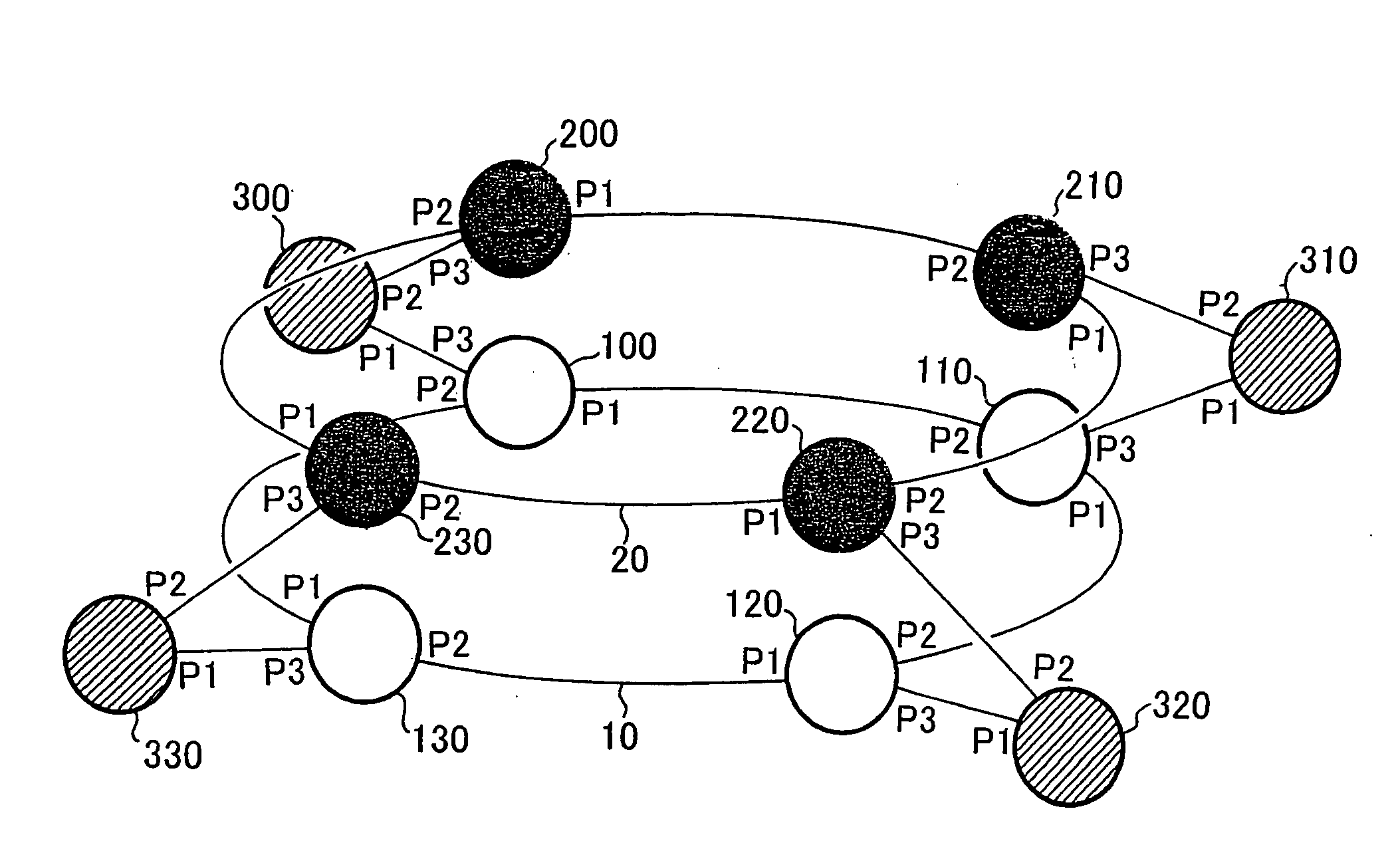
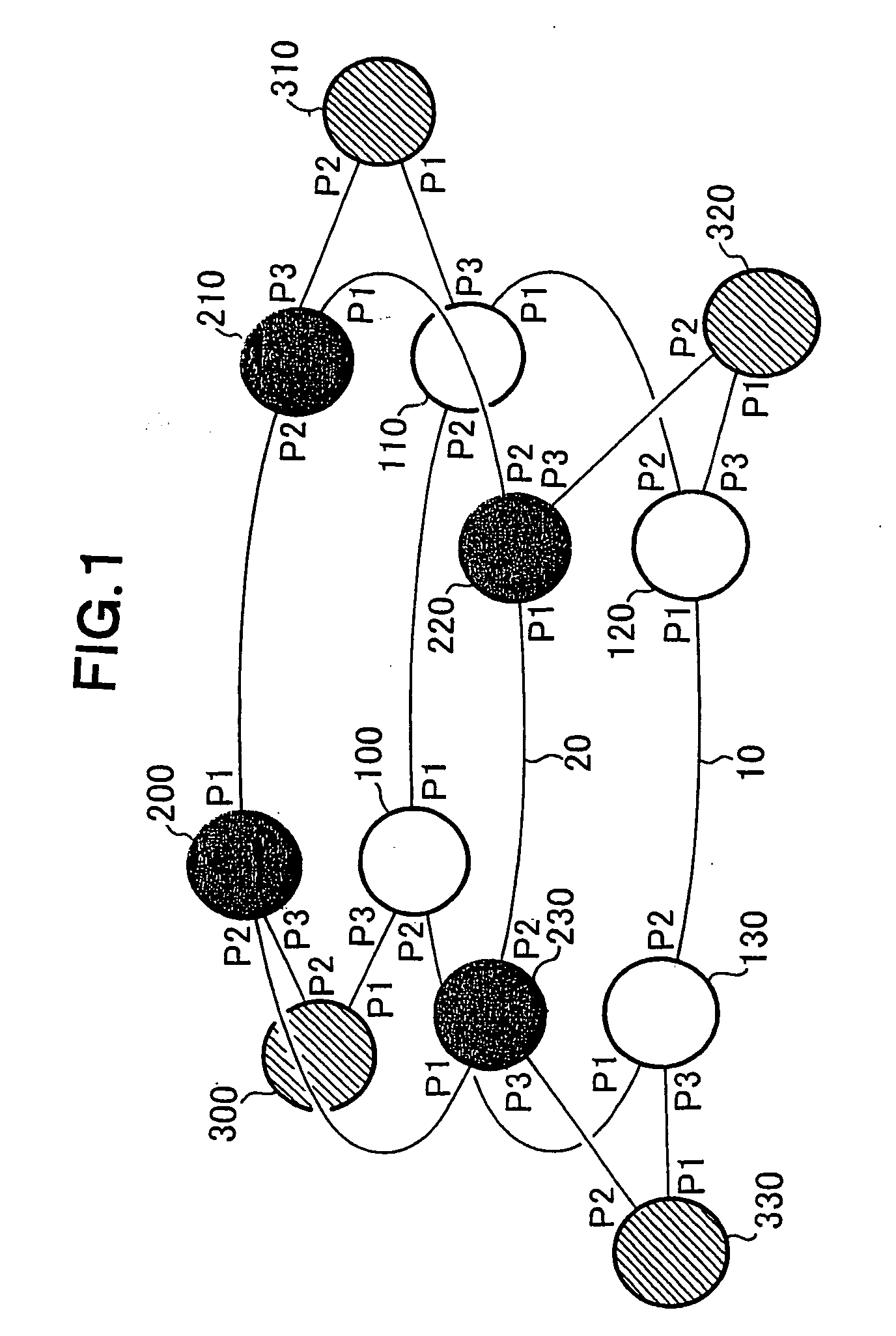
[0115]FIG. 1 is an explanatory view showing a first embodiment of a communication system according to the present invention. A communication system according to the first embodiment has an RPR network 10 including RPR nodes 100 to 130, an RPR network 20 including RPR nodes 200 to 230, and nodes 300 to 330 each of which is connected to both one RPR node belonging to the RPR network 10 and one RPR node belonging to the RPR network 20. As described above, the RPR network is a network to which the RPR has been applied.

[0116]The RPR nodes 100 to 130 and 200 to 230 not only operate according to “IEEE Std 802.17” but also perform other operations (operation for achieving an object of the present invention). In the present embodiment, a common terminal (one of the nodes 300 to 320) is located under each pair of nodes belonging to the networks 10 and 20 respectively. To locate one terminal under the RPR node means that a terminal that does not belong to a ring network to which the RPR node b...

second embodiment

[0260]A second embodiment of the present invention will be described below with reference to the accompanying drawings. A configuration of a communication system according to the present invention is the same as that of the first embodiment shown in FIG. 1 except for a point that a frame that the RPR node exchanges with its dependent terminal via the port P3 is not the frame segment but the RPR frame.

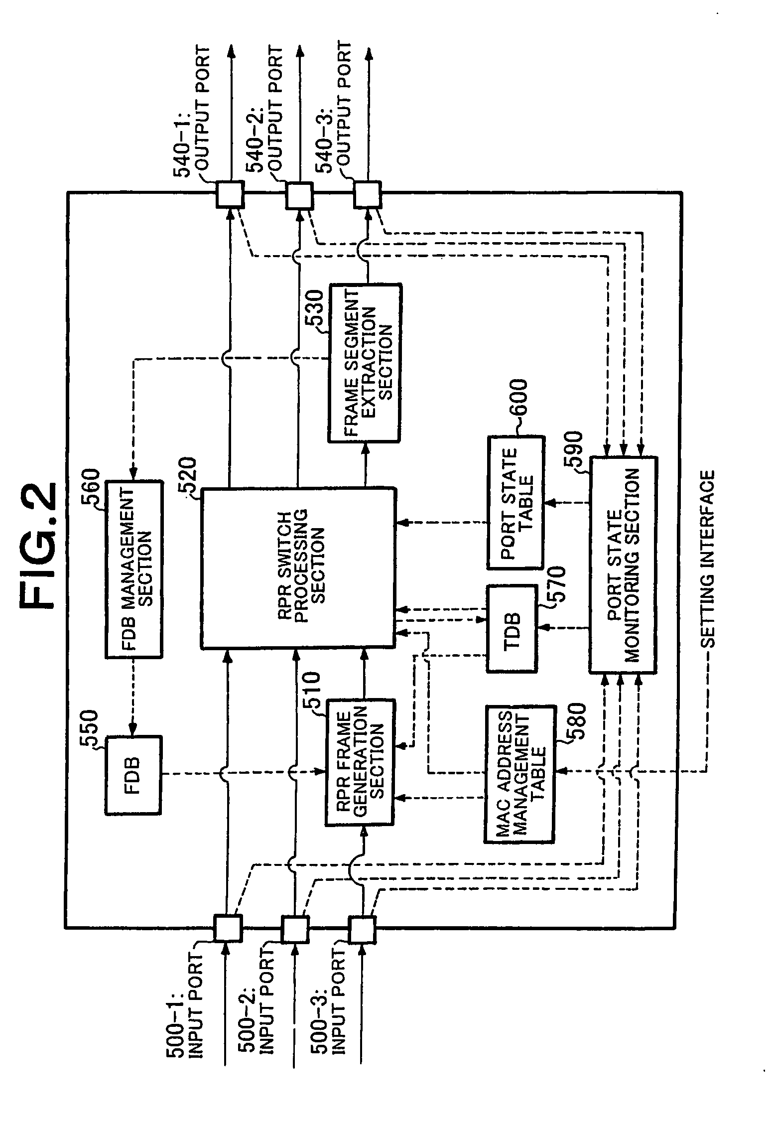
[0261]Configurations of the RPR node and a node serving as the dependent terminal of the RPR node will next be described. FIG. 17 is a block diagram showing a configuration example of the RPR node 100 in the second embodiment. Although the RPR node 100 is taken as an example in descriptions below, the same descriptions may apply to the other RPR nodes 110 to 130 and 200 to 230.

[0262]As shown in FIG. 17, the RPR node 100 according to the present embodiment differs from the RPR node of the first embodiment shown in FIG. 2 in that it does not include the RPR frame generation section 510, f...

third embodiment

[0287]A third embodiment of the present invention will be described below with reference to the accompanying drawings. FIG. 21 is an explanatory view showing a configuration example of a communication system according to the present embodiment. The communication system shown in FIG. 21 differs from the communication system according to the first embodiment shown in FIG. 1 in that RPR nodes under which the same terminal is located are connected by a communication link. As shown in FIG. 21, each of the RPR nodes 100 to 130 and 200 to 230 has a port P4 in addition to the ports P1 to P3. The port P4 is a port for exchanging topology information between RPR nodes belonging to different RPR networks.

[0288]Configurations of the RPR node and a node serving as the dependent terminal of the RPR node will next be described. FIG. 22 is a block diagram showing a configuration example of the RPR node 100 in the present embodiment. Although the RPR node 100 is taken as an example in descriptions b...


PUM


Abstract

It is possible to increase the communication system transmission capacity flexibly and at low cost in accordance with a communication system traffic amount. A terminal connected to a plurality of networks distributes a plurality of frame segments generated by dividing a single frame to the plurality of networks connected to the local terminal transmits them. Further, the terminal reconstructs the original frame from the plurality of frame segments generated by dividing the single frame. It should be noted that each of the frame segments contains division configuration information indicating how the frame has been divided (the number of divisions and the order of the frame segments) and also contains information required for performing MAC address learning for determining the path to the destination terminal.

Description

TECHNICAL FIELD[0001]The present invention relates to a communication system, a node, a terminal, and a communication method and program and, more particularly, to a communication system having high scalability on transmission capacity and a terminal, a node, a communication method, a terminal program, and a node program for use in realizing the communication system.BACKGROUND ART[0002]In recent years, data traffic has been explosively increased due to the recent rapid expansion of the Internet and, therefore, transmission capacity of a backbone communication system has been insufficient to support the increased traffic demand. When the transmission capacity of the communication system becomes insufficient, congestion frequently occurs, resulting in intermittent communication or disruption of communication. Thus, there is demanded a technique capable of increasing transmission capacity of a communication system so as to continuously provide stable communication.[0003]Generally, in o...

Claims


Application Information

Patent Timeline
IPC IPC(8): H04L12/56H04L47/43
CPCH04L45/00H04L12/437
Inventor OGASAHARA, DAISAKUSAKAUCHI, MASAHIRO
Owner NEC CORP
Why Eureka
Try Eureka