Image forming apparatus

Inactive Publication Date: 2010-09-09
CANON KK
View PDF4 Cites 6 Cited by
  • Summary
  • Abstract
  • Description
  • Claims
  • Application Information

AI Technical Summary

Benefits of technology

[0016]The present invention provides an image forming apparatus capable of suppressing position shifting of an image without causing upsizing of the apparatus.

Problems solved by technology

However, in addition to the element which varies in a long time, color shifting includes an element which fluctuates in a short time to cause fluctuation of a rotation member.
In other words, since correction is performed on the next image forming after detecting the color registration shifting of an image which was formed in the past, fluctuation in a short time cannot be corrected.
However, when the color registration shifting is corrected by controlling the rotation speed of the photosensitive drum as disclosed in Japanese Patent Laid-open No. 2004-145077, such problems as described below occur.
There has been a problem that the position correction amount exceeds a position correction control range when the position correction amount is oscillated.
However, the complete stop of the image forming operation results in reduction in throughput of image forming.
However, since the mass of the exposure portion is large, high-speed fine move of the exposure portion integral with the photosensitive drum unavoidably results in the upsizing and higher cost of the movement mechanism.

Method used


Image

  • Image forming apparatus
  • Image forming apparatus
  • Image forming apparatus

Examples


first embodiment

General Overview of Image Forming Apparatus

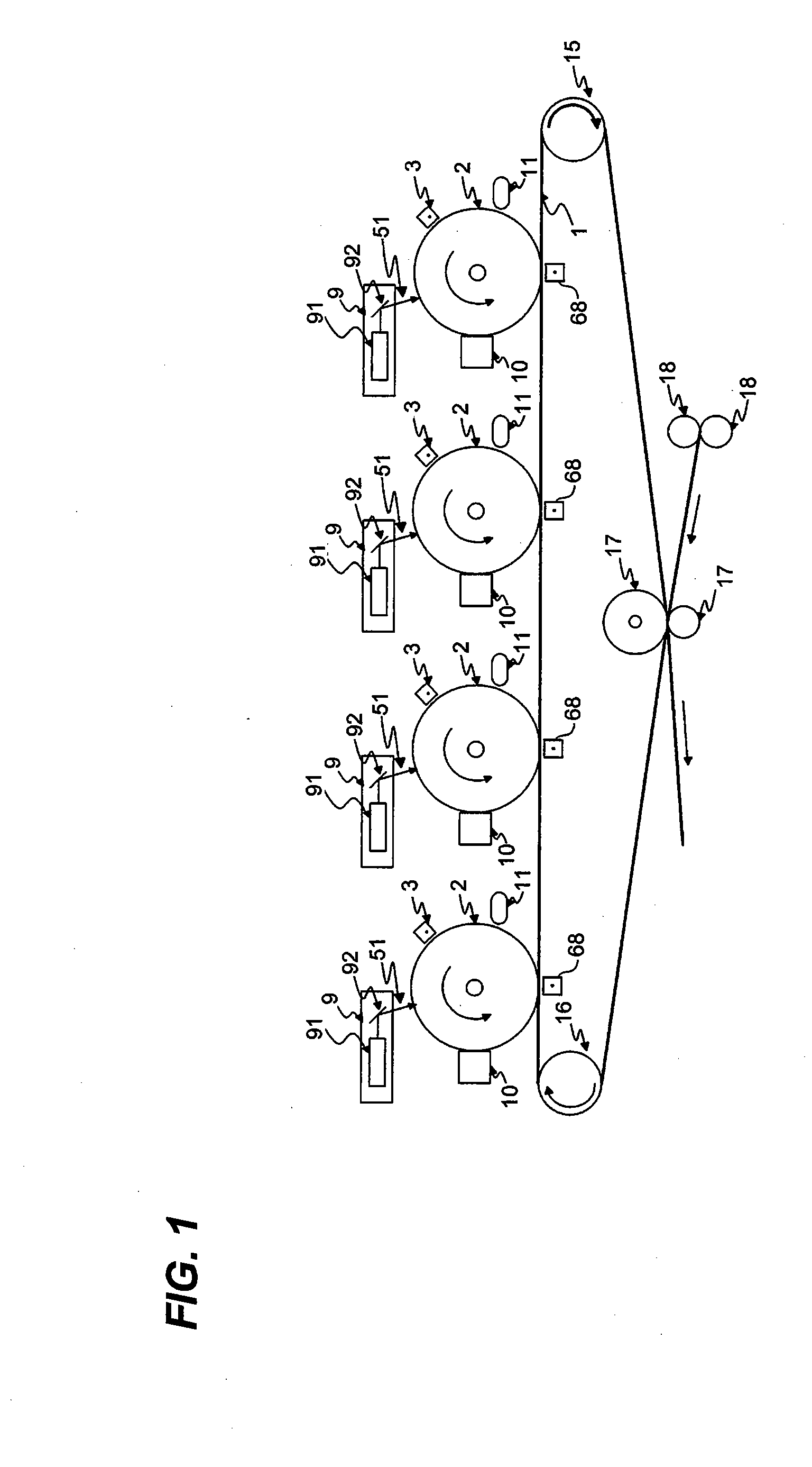
[0036]FIG. 1 is a schematic view of the entire configuration of an image forming apparatus. As illustrated in FIG. 1, the image forming apparatus of the present embodiment is a color image forming apparatus of a tandem type having four photosensitive drums (i.e., photosensitive members).

[0037]The image forming apparatus according to the present embodiment includes an intermediate transfer belt 1 turning to move at constant speed and photosensitive drums 2 for respective four colors rotating at constant angular speed.

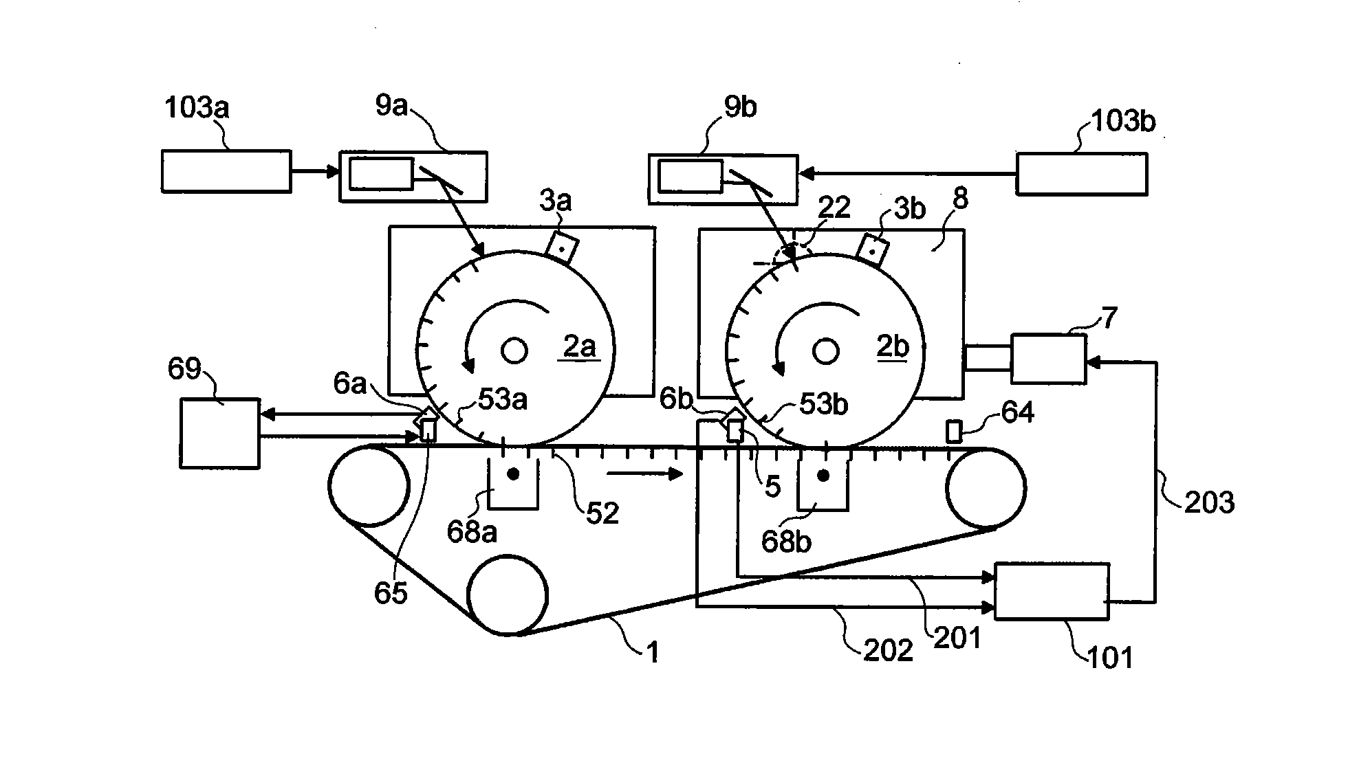
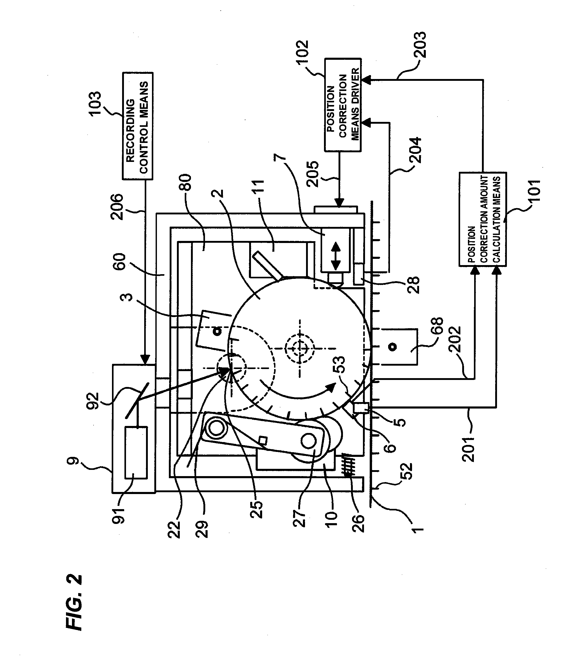
[0038]There are provided a primary charger 3, an exposure portion 9, a laser optical system 91, a reflection mirror 92, a development portion 10 and a cleaner 11 at the vicinity of the photosensitive drum 2. The exposure portion 9 also functions as a position information recording portion.

[0039]The intermediate transfer belt 1 is extended by a drive roller 15 and a driven roller 16. Further, at the intermediate transfer belt 1, ...

second embodiment

[0133]A second embodiment will be described below with reference to FIG. 13. FIG. 13 is a sectional view of the image forming portion of the second embodiment viewing from the end portion direction of the photosensitive drum 2. The same numeral is used for the common structure to the abovementioned embodiment and the description will not be repeated. In the present embodiment, only the configuration of a drum urging portion to continuously urge the photosensitive drum 2 in one direction is differ from the embodiment of FIG. 2.

[0134]A drum urging portion 301 in the present embodiment pulls a slide plate 302 which is coupled to the photosensitive drum shaft 23 via a bearing 303 with a tension spring 304. Accordingly, the photosensitive drum 2 is urged to one direction. The drum urging portion 301 is arranged respectively to both sides of the photosensitive drum 2.

[0135]An elongated hole 306 is formed at the slide plate 302. The elongated hole 306 is engaged with a guide pin 305 arrang...


PUM


Abstract

The image forming apparatus includes a plurality of photosensitive members, a plurality of exposure portions to perform exposure on the plurality of photosensitive members, a development portion to form a toner image at the plurality of photosensitive members, a transfer medium to which the respective toner images formed on the plurality of photosensitive members are sequentially transferred so as to form an image, and a position correction portion to perform position correction by moving at least one photosensitive member among the plurality of photosensitive members, and the position correction of the photosensitive member is performed by swinging the photosensitive member by the position correction portion having a line on a circumference surface of the photosensitive member corresponding to an exposure position of the exposure portion as the center axis.

Description

BACKGROUND OF THE INVENTION[0001]1. Field of the Invention[0002]The present invention relates to image forming apparatuses having a plurality of image forming portions, such as color printers and color copying machines. In particular, the present invention relates to an image forming apparatus which performs control of color shifting.[0003]2. Description of the Related Art[0004]In the related art, there has been image forming apparatuses which perform color shifting correction (e.g., see Japanese Patent Laid-open Nos. S64-6981, H5-241457, and 2004-145077).[0005]In the image forming apparatus in accordance with Japanese Patent Laid-open No. S64-6981, a rewritable information writing portion is disposed respectively on each surface of a photosensitive drum and an intermediate transfer belt in the sub-scanning direction. The speed difference between the photosensitive drum and the intermediate transfer belt is detected by detecting information written in the information writing portion...

Claims


Application Information

Patent Timeline
IPC IPC(8): G03G15/01
CPCG03G15/0131G03G15/0194G03G2215/0158G03G15/5008
Inventor SHIHOH, MAKOTOITO, HIROSHISHIGEMURA, YOSHIHIRO
Owner CANON KK
Why Eureka
Try Eureka