Plate member for fuel cell, manufacturing method of the plate member, and fuel cell

Active Publication Date: 2010-09-09
TOYOTA JIDOSHA KK
View PDF2 Cites 13 Cited by
  • Summary
  • Abstract
  • Description
  • Claims
  • Application Information

AI Technical Summary

Benefits of technology

[0023]According to such a manufacturing method, the edge of the first covering portion is formed, and then this edge together with the portion around the edge of the first covering portion is covered with the second covering portion, so that the pl

Problems solved by technology

In a case where such an edge is present in a portion which comes in contact with a fluid, a portion around the edge easily det

Method used


Image

  • Plate member for fuel cell, manufacturing method of the plate member, and fuel cell
  • Plate member for fuel cell, manufacturing method of the plate member, and fuel cell
  • Plate member for fuel cell, manufacturing method of the plate member, and fuel cell

Examples


first embodiment

[0034]A first embodiment of the present invention will hereinafter be described with reference to FIGS. 1 to 5B.

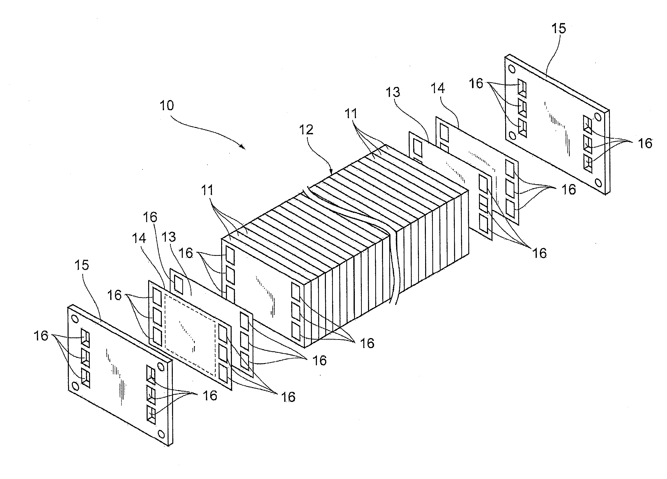
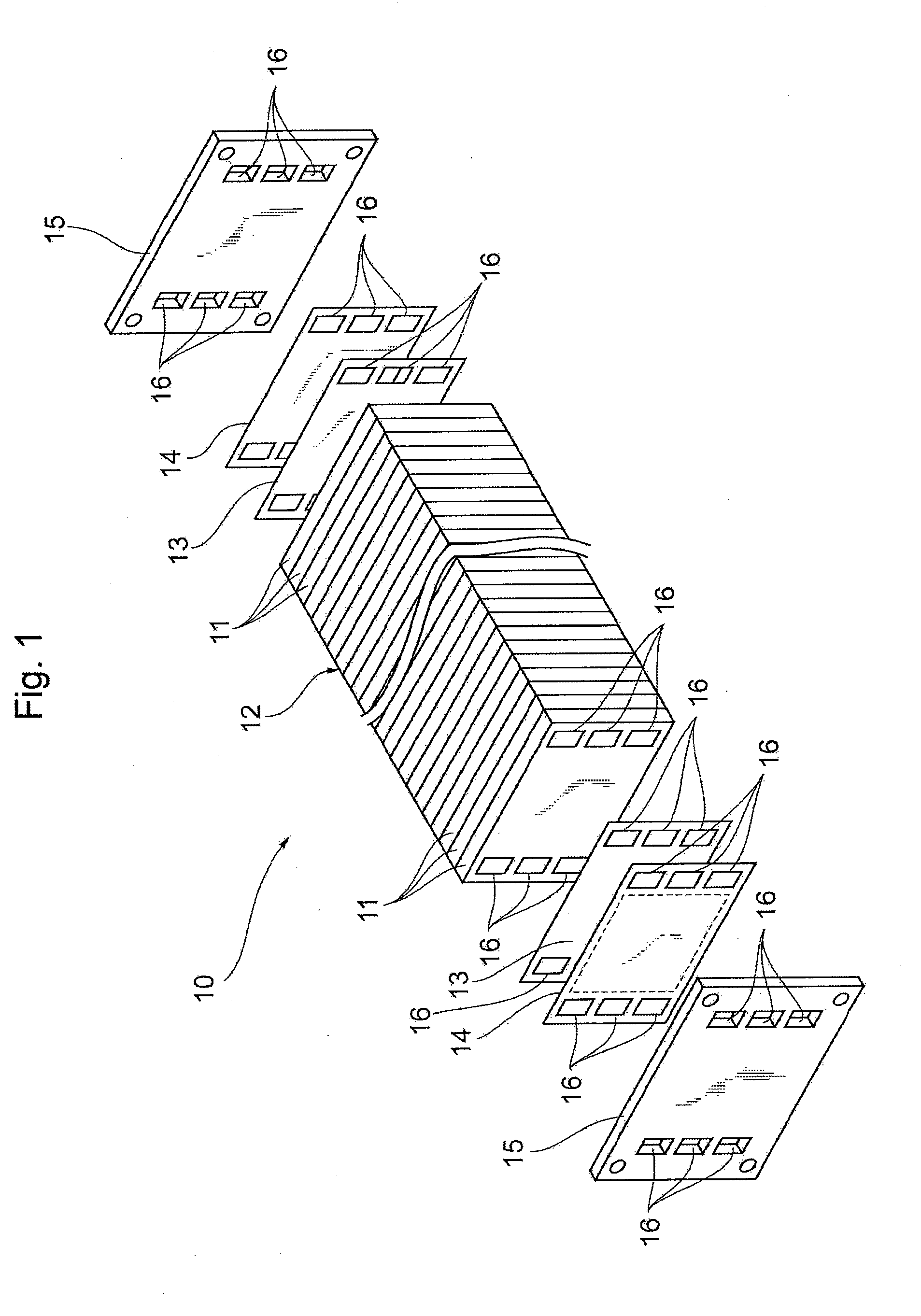
[0035]First, a constitution of a fuel cell 10 according to the present embodiment will be described. As shown in FIG. 1, the fuel cell 10 has a stack 12 in which a large number of cells 11 to generate a power owing to an electrochemical reaction are laminated, and has a constitution in which collector plates 13, insulating plates 14 and end plates 15 are laminated and integrated on opposite ends in a laminating direction. The stack 12 and the plates 13, 14 and 15 are provided with three sets of manifolds 16 for supplying and discharging a fuel gas, an oxidizing gas and cooling water so that the manifolds extend through the stack and the plates in the laminating direction. The cells 11 correspond to one embodiment of one fuel cell in the present invention, and the stack 12 corresponds to one embodiment of a laminate in the present invention.

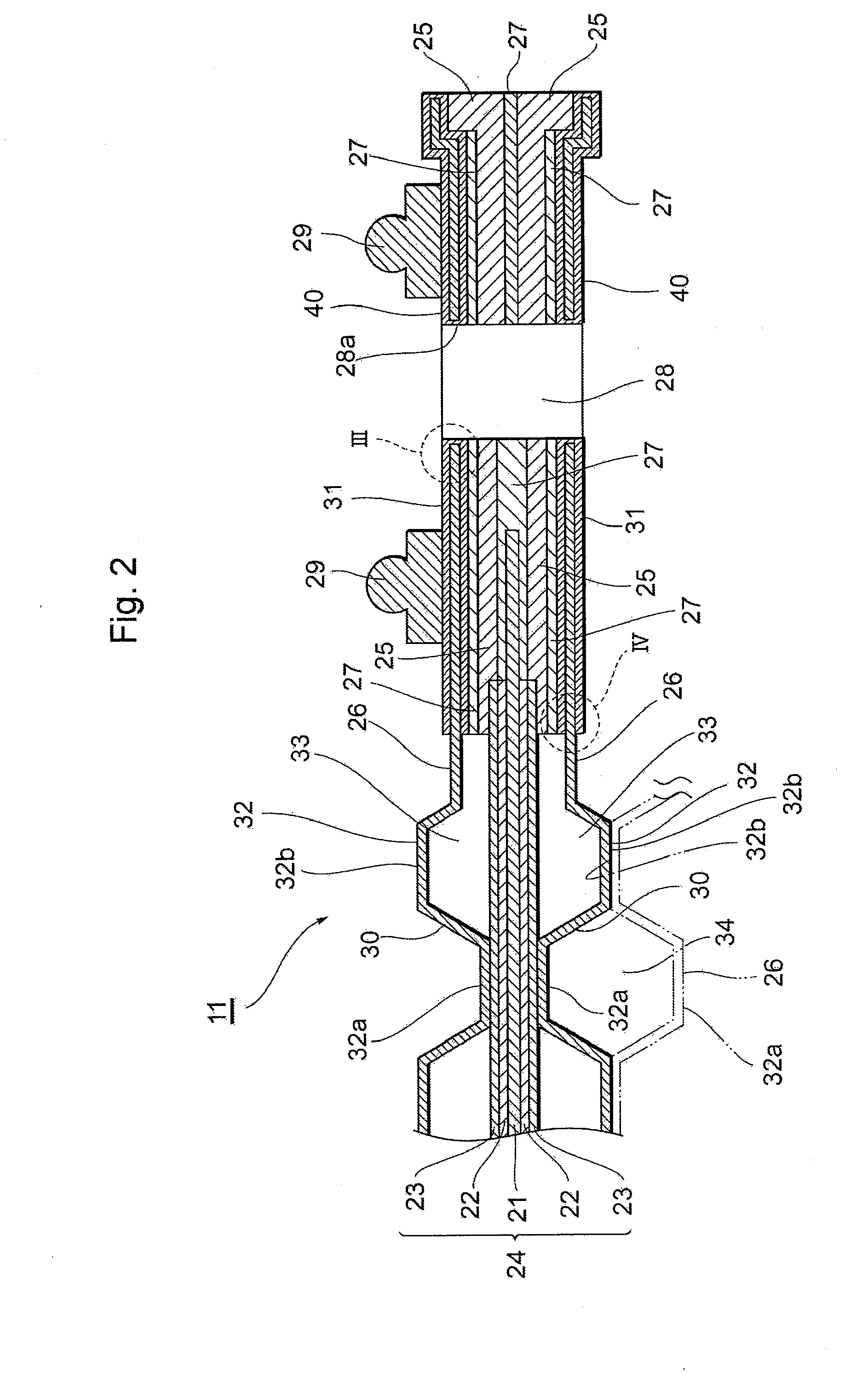
[0036]As shown in FIG. 2, each ce...

second embodiment

[0058]Next, a separator according to a second embodiment of the present invention will be described with reference to FIG. 6. In the separator according to the present embodiment, the edges 41a, 41b of the first covering portions 41 according to the first embodiment are covered with second covering portions 42c, 42d different from those of the first embodiment. The other constitution is substantially the same as that of the first embodiment.

[0059]Each of the second covering portions 42c, 42d of the present embodiment is a filling material formed of an adhesive. The second covering portion 42c covers the edge 41a of the first covering portion 41 on an inner wall surface of a through hole 28 for a manifold and a region surrounded with the edge 41a, and the second covering portion 42d covers the edge 41b of the first covering portion 41 on the side of one surface of a base material 43 and a region surrounded with the edge 41b.

[0060]Even in the separator according to the above embodime...

third embodiment

[0061]Next, a separator according to a third embodiment of the present invention will be described with reference to FIG. 7. In the separator according to the present embodiment, edges 41c of first covering portions 41 on the side of a power generating region 30 are formed away from edges of plated metals 26a, and the other constitution is substantially the same as that of the first embodiment.

[0062]Even in such a separator, in the same manner as in the first embodiment, deterioration of portions around the edges 41c formed on the first covering portions 41 due to a fluid can highly be prevented. In addition, the edges 41c of the first covering portions 41 do not have to be precisely positioned during formation, and a boundary portion between the first covering portions 41 and the plated metals 26a can securely be covered. Therefore, the separator can more easily be manufactured with good operability.


PUM


Abstract

There is disclosed a plate member for a fuel cell which is laminated together with a membrane-electrode assembly to constitute a fuel cell having cells and is provided with a channel forming portion which forms a fluid channel to supply and discharge a fluid to/from the membrane-electrode assembly and/or the cells. The plate member for the fuel cell includes a first covering portion which covers the channel forming portion, and a second covering portion which covers an edge of the first covering portion together with a portion around the edge of the first covering portion.

Description

TECHNICAL FIELD[0001]The present invention relates to a plate member for a fuel cell, a manufacturing method of the plate member, and a fuel cell.BACKGROUND ART[0002]As a fuel cell, a constitution is suggested in which collector plates, insulating plates and end plates are laminated on opposite sides of a stack (a laminate) constituted of a plurality of layers of cells (unitary cells) each formed by holding a membrane-electrode assembly between plate-like separators on the opposite sides. In such a fuel cell, when a fuel gas and an oxidizing gas are supplied from the outside to the membrane-electrode assemblies of the cells, a power is generated in the cells owing to an electrochemical reaction to discharge a surplus gas, a water vapor, produced water and the like from the cells. Furthermore, a heat medium such as cooling water is supplied and discharged between the cells.[0003]A plate member such as the separator, the collector plate, the insulating plate and the end plate constitu...

Claims


Application Information

Patent Timeline
IPC IPC(8): H01M8/10H01M8/00
CPCH01M8/0228H01M8/0245H01M8/0247Y02E60/50H01M8/0273H01M8/242H01M2008/1095H01M8/0258Y02P70/50H01M8/2483H01M8/0267H01M8/2404H01M8/2457H01M8/241
Inventor IIZUKA, KAZUTAKA
Owner TOYOTA JIDOSHA KK
Why Eureka
Try Eureka