

Mobile communication base station antenna
a mobile communication and antenna technology, applied in the direction of antennas, polarised antenna unit combinations, antenna details, etc., can solve the problems of increasing the total shortening the number of frequencies, and further increasing the installation area of the mobile communication base station antenna. , to achieve the effect of reducing the cost and increasing the data communication capacity
- Summary
- Abstract
- Description
- Claims
- Application Information
AI Technical Summary
Benefits of technology
Problems solved by technology
Method used
Image

Examples
first preferred embodiment
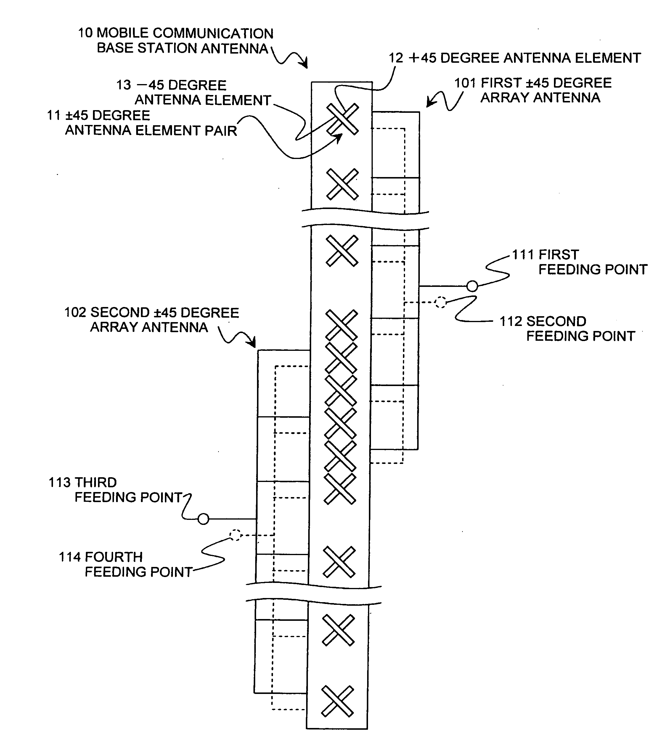
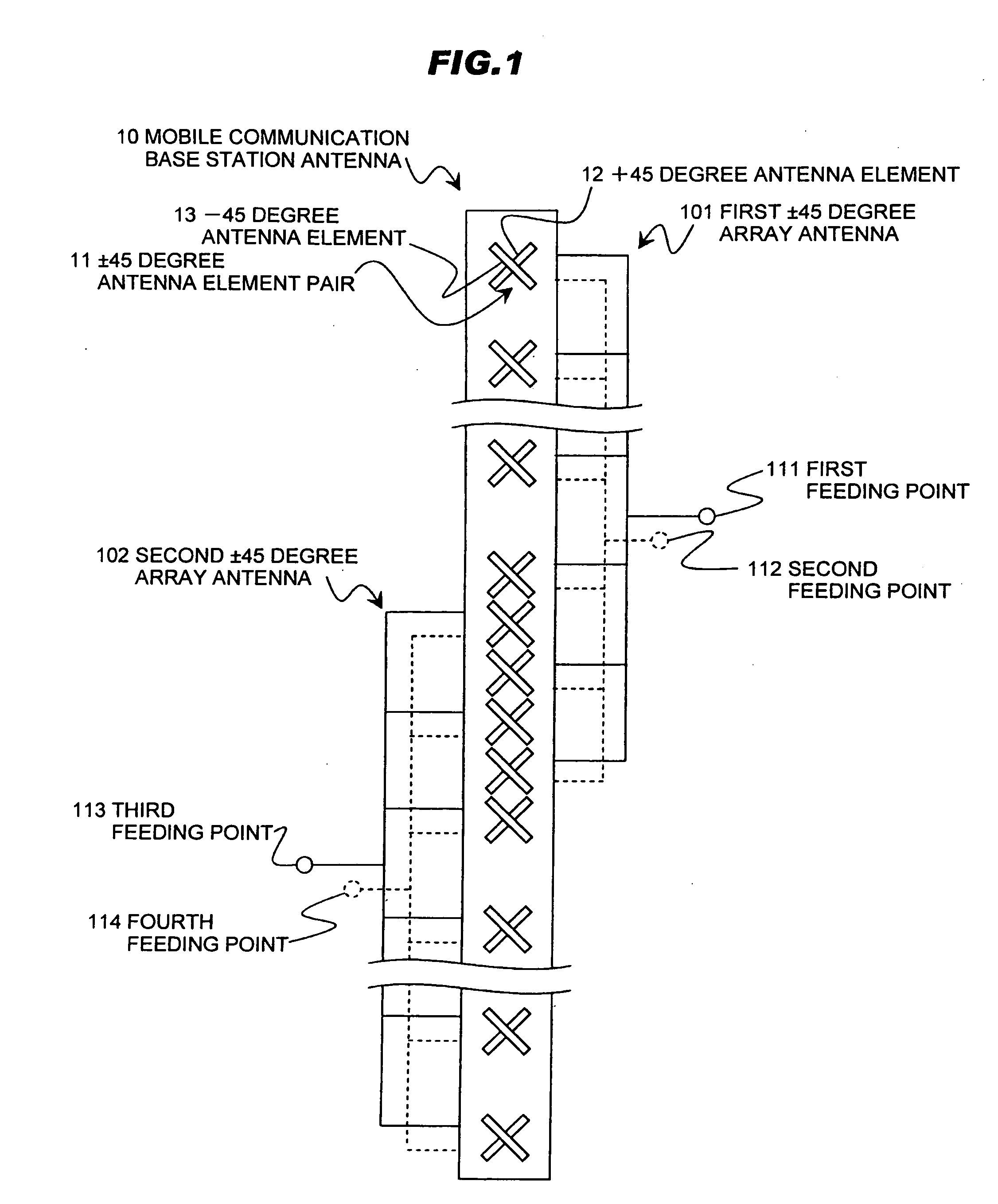
[0057]FIG. 1 is a schematic diagram of the mobile communication base station antenna in the first preferred embodiment according to the invention.
[0058]As shown in FIG. 1, a mobile communication base station antenna 10 comprises two or more array antennas (a first ±45 degree array antenna 101 and a second ±45 degree array antenna 102 in FIG. 1), and respective array antennas 101, 102 are arranged in a vertical plane. The mobile communication base station antenna 10 is such configured that antenna element pairs included in one of adjacent array antennas and antenna element pairs included in the other one of the adjacent array antenna included are alternately arranged at least in a part between the adjacent array antennas. In this embodiment, a case where two array antennas (±45 degree array antennas) 101, 102 are arranged in the vertical plane as shown in FIG. 1 will be explained.
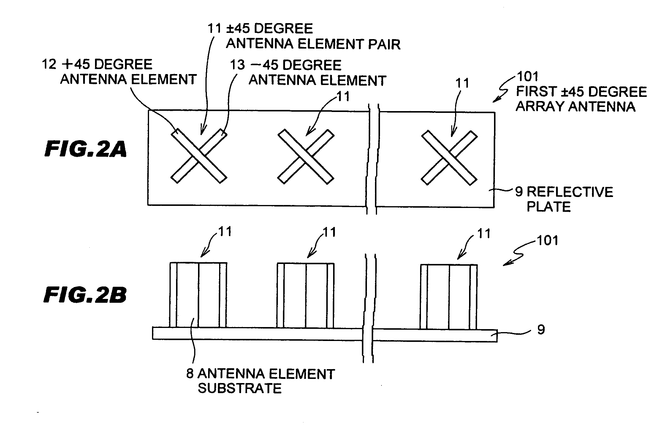
[0059]In the ±45 degree array antennas 101, 102 that are the two array antennas, a plurality of antenna e...
second embodiment
[0085]FIG. 6 is a schematic diagram of a mobile communication base station antenna in the second preferred embodiment according to the invention.
[0086]Referring to FIG. 6, a mobile communication base station antenna 20 is similar to the mobile communication base station antenna 10 of FIG. 1, except that the array antennas (±45 degree array antennas) 101, 102 in which the ±45 degree antenna element pairs 11 are linearly arranged in the vertical plane are replaced with array antennas (horizontal-vertical polarization array antennas) 201, 202 in which horizontal-vertical polarization antenna element pairs 21 are linearly arranged in the vertical plane. The horizontal-vertical polarization antenna element pair 21 comprises a combination of one antenna element (vertical polarization antenna element) 22 arranged in the vertical direction and another antenna element (horizontal polarization antenna element) 23 in the horizontal direction.
[0087]In this embodiment, an electric power is fed f...
third embodiment
[0089]FIG. 7 is a schematic diagram of a mobile communication base station antenna in the third preferred embodiment according to the invention.
[0090]Referring to FIG. 7, a mobile communication base station antenna 30 is similar to the mobile communication base station antenna 10 of FIG. 1, except that an array antennas (±45 degree array antenna) 103 in which the ±45 degree antenna element pairs 11 are linearly arranged in the vertical plane and an array antenna (horizontal-vertical polarization array antenna) 203 in which the horizontal-vertical polarization antenna element pairs 21 are linearly arranged in the vertical plane are arranged in the same vertical plane.
[0091]In this embodiment, an electric power is fed from the first feeding point 311 to the +45 degree antenna element 12 composing the ±45 degree array antenna 103 by a feeding line expressed in a solid line, fed from the second feeding point 312 to the −45 degree antenna element 13 composing the ±45 degree array antenna...
PUM
 Abstract
Description
Claims
Application Information