Mobile Communication base station antenna

a mobile communication and antenna technology, applied in the direction of antennas, antenna details, antenna feed intermediates, etc., can solve the problems of short frequency range, increased installation occupied area of mobile communication base station antenna in total, and increased installation occupied area of mobile communication base station antenna

Inactive Publication Date: 2010-05-27
HITACHI CABLE
View PDF4 Cites 9 Cited by
  • Summary
  • Abstract
  • Description
  • Claims
  • Application Information

AI Technical Summary

Benefits of technology

[0017]Therefore, an object of the present invention is to solve the above problem and to provide a mobile communication base station antenna for realizing ...

Problems solved by technology

However, as a result of sudden increase of mobile communication users in accordance with spread of the mobile communication for late years, there is a problem in that the number of frequencies becomes short due to call requests more than capacity of frequency channels assigned to the mobile communication.
However, in the conventional antenna devices proposed by JP-A 2001-313525 and Nishimori et al, there is a problem in that installation occupied area of the mobile communication base station antenna in total is increased since the array antennas are disposed linearly or annularly.
In addition, when the array antennas are disposed linearly or annularly, there is another problem in that the installation occupied area of the mobile communication base station antenna is further increased since a large space (interval) between adjacent array antennas is required so as to obtain a space di...

Method used


Image

  • Mobile Communication base station antenna
  • Mobile Communication base station antenna
  • Mobile Communication base station antenna

Examples


first preferred embodiment

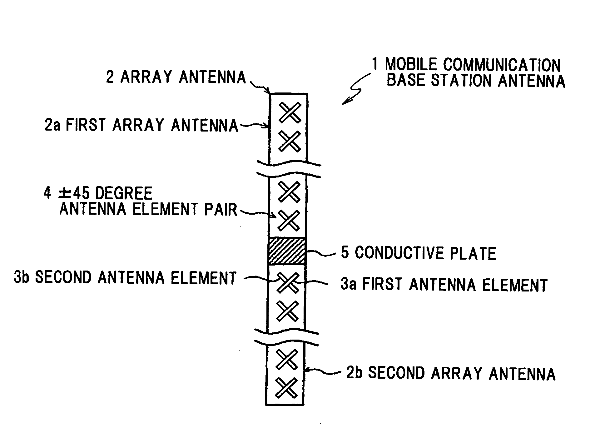
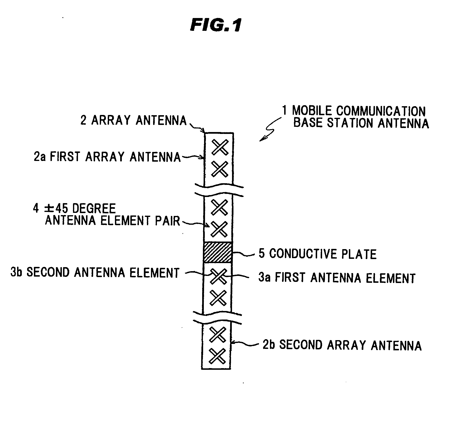
[0046]FIG. 1 is a schematic diagram of the mobile communication base station antenna in a first preferred embodiment according to the invention.

[0047]As shown in FIG. 1, a mobile communication base station antenna 1 comprises two or more array antennas 2 (two array antennas 2 in FIG. 1), and respective array antennas 2 are arranged in a vertical direction with a predetermined interval (distance). In this preferred embodiment, the mobile communication base station antenna 1, in which a first array antenna 2a and a second array antenna 2b are arranged in the vertical direction, will be explained.

[0048]The first and second array antennas 2a, 2b are connected with each other via a conductive plate 5. The conductive plate 5 is provided as a common ground potential (GND potential) for the first and second array antennas 2a, 2b. The first and second array antennas 2a, 2b are located to be separated from each other with a predetermined distance in the vertical direction.

[0049]Each of the fi...

second preferred embodiment

[0080]Next, a mobile communication base station antenna 61 in a second preferred embodiment will be explained below.

[0081]FIG. 8 is a schematic diagram of the mobile communication base station antenna 61 in the second preferred embodiment according to the present invention. In the second preferred embodiment, the array antenna 2 in which the ±45 degree antenna element pairs 4 are arranged in the array shape in the mobile communication base station antenna 1 shown in FIG. 1 is replaced with an array antenna 63 in which horizontal-vertical antenna element pairs 62 are arranged in array shape. In the horizontal-vertical antenna element pair 62, a first antenna element (vertical antenna element) 64a is located vertically and a second antenna element (horizontal antenna element) 64b is located horizontally.

[0082]In the mobile communication base station antenna 61, the ±45 degree antenna element pairs 4 are replaced with the horizontal-vertical antenna element pairs 62. Therefore, it is p...

third preferred embodiment

[0083]Next, a mobile communication base station antenna 71 in a third preferred embodiment will be explained below.

[0084]FIG. 9 is a schematic diagram of the mobile communication base station antenna 71 in the third preferred embodiment according to the present invention.

[0085]In the mobile communication base station antenna 71 as shown in FIG. 9, the array antenna 2 in which the ±45 degree antenna element pairs 4 are arranged in the array shape and the array antenna 63 in which the horizontal-vertical antenna element pairs 62 are arranged in the array shape are arranged in the vertical direction.

[0086]Since a polarization direction of the array antenna 2 is different from that of the array antenna 63, it is possible to reduce the antenna correlation coefficient between the array antenna 2 and the array antenna 63 by arranging the array antenna 2 and the array antenna 63 to be adjacent to each other, compared with the first preferred embodiment in which the array antennas 2 are adja...


PUM


Abstract

A mobile communication base station antenna has two or more array antennas. Each of the array antennas includes a plurality of antenna element pairs arranged in array shape. Each of the antenna element pairs includes two antenna elements located to be orthogonal to each other. Polarization characteristics of the two antenna elements are orthogonal to each other. The array antennas are arranged with a predetermined distance in a vertical direction.

Description

[0001]The present application is based on Japanese Patent Application No. 2008-301207 filed on Nov. 26, 2008, the entire contents of which are incorporated herein by reference.BACKGROUND OF THE INVENTION[0002]1. Field of the Invention[0003]The present invention relates to a dual-polarized antenna and an array antenna, more particularly, to a mobile communication base station antenna for realizing a Space Division Multiple Access (SDMA).[0004]2. Related Art[0005]Technique such as Frequency Division Multiple Access (FDMA), Time Division Multiple Access (TDMA), or Code Division Multiple Access (CDMA) has been proposed to realize a simultaneous connection of plural users in a base station to be used for mobile communication, and has been introduced into commercial systems.[0006]However, as a result of sudden increase of mobile communication users in accordance with spread of the mobile communication for late years, there is a problem in that the number of frequencies becomes short due t...

Claims


Application Information

Patent Timeline
IPC IPC(8): H01Q21/00H01Q9/16
CPCH01Q1/246H01Q21/26H01Q21/08
Inventor SHIMIZU, TAKAYUKIMURANO, SHINSUKEANDO, TOSHIYUKI
Owner HITACHI CABLE
Why Eureka
Try Eureka