Ballistic Groin Protector

a technology of groin protector and ballistic shield, which is applied in the direction of protective clothing, protective equipment, weapons, etc., can solve the problems of sacrificing its protective function and causing discomfort to the wearer, and the protective element that is too sti

Inactive Publication Date: 2010-09-16
LINEWEIGHT
View PDF33 Cites 17 Cited by
  • Summary
  • Abstract
  • Description
  • Claims
  • Application Information

AI Technical Summary

Benefits of technology

[0009]The ballistic protective element of the present invention is preferably a compound curved sheet comprised of a stack of multiple layers of ballistic material, for example material of Kevlar® fibers, or Spectra® fiber material. The stack may be stitched around the periphery, to obtain the desired level of stiffening, a more or less thick plastic stiffening shape may be formed together with the layers of ballistic material. The ballistic protective element is preferably somewhat compliant and not so stiff as to excessively interfere with movement of the wearer. The ballistic element may be enclosed within a fabric bag and suspended from a belt, and have a rearwardly opening cup shape to serve to protect the groin of a wearer.
[0010]Because of the compound shape, the ballistic protective element can be better positioned to protect the guarded wearer, staying closer to the protected body when exposed to a threat, yet at the same time, the compliant capacity of the element makes it less likely to interfere significantly with the wearer's movements, especially when coming rapidly in contact with some obstacle.
[0011]It is a feature of the present invention to provide a ballistic protective element which is curved to stay close to a protected body part but which is not so rigid as to be unnecessarily uncomfortable.

Problems solved by technology

However, the shape of the prior art element 10 which is suspended from the vest, is spaced from the wearer's body, and in the case of an explosion can be displaced or detached from the wearer, thus sacrificing its protective function.
Yet a protective element that is too stiff can be uncomfortable to the wearer, especially when encountering obstacles or in situations requiring active movement.

Method used


Image

  • Ballistic Groin Protector
  • Ballistic Groin Protector
  • Ballistic Groin Protector

Examples


Embodiment Construction

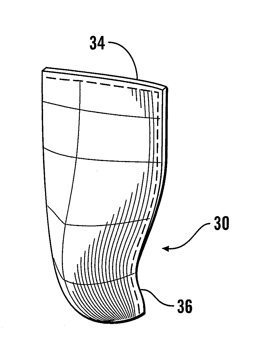
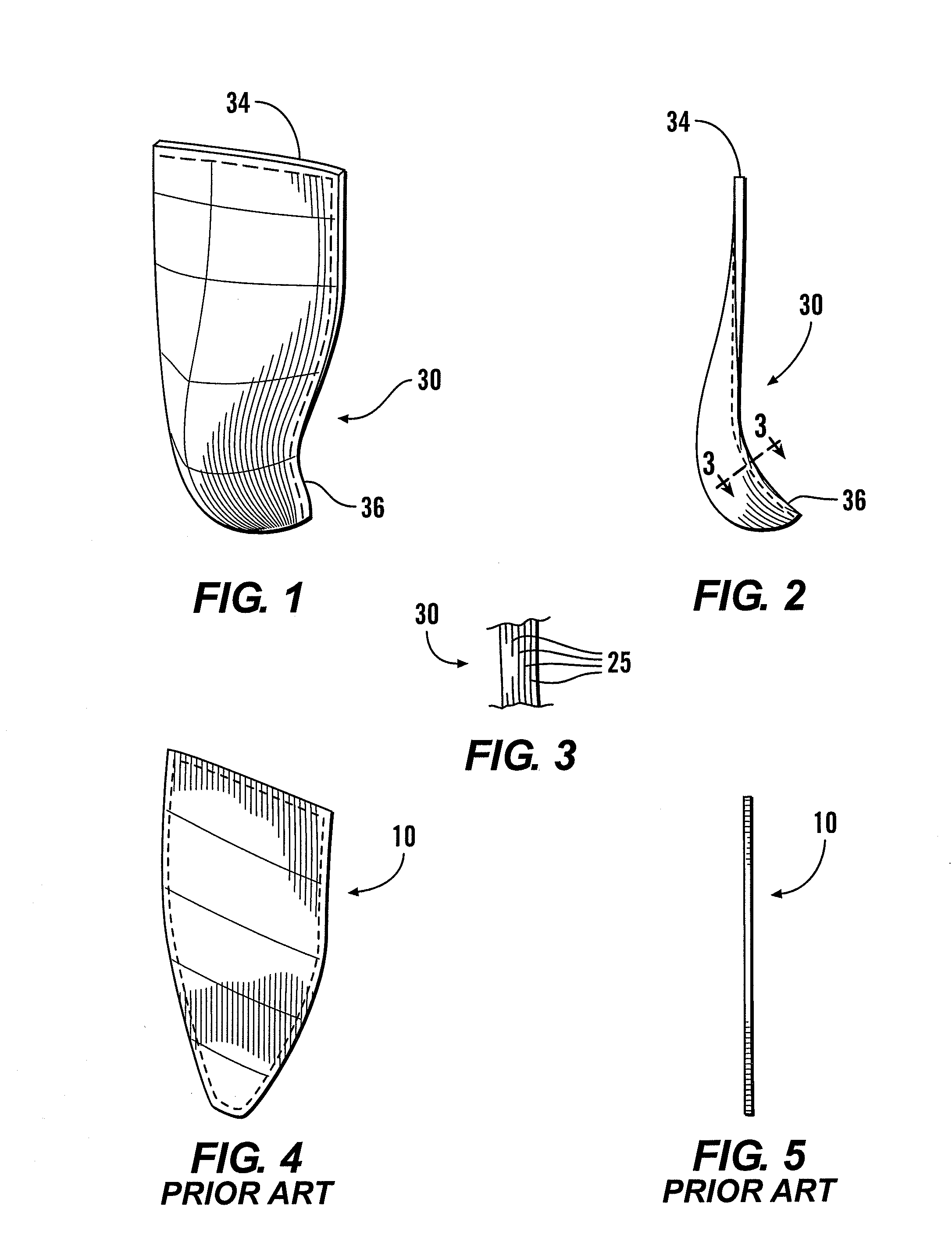
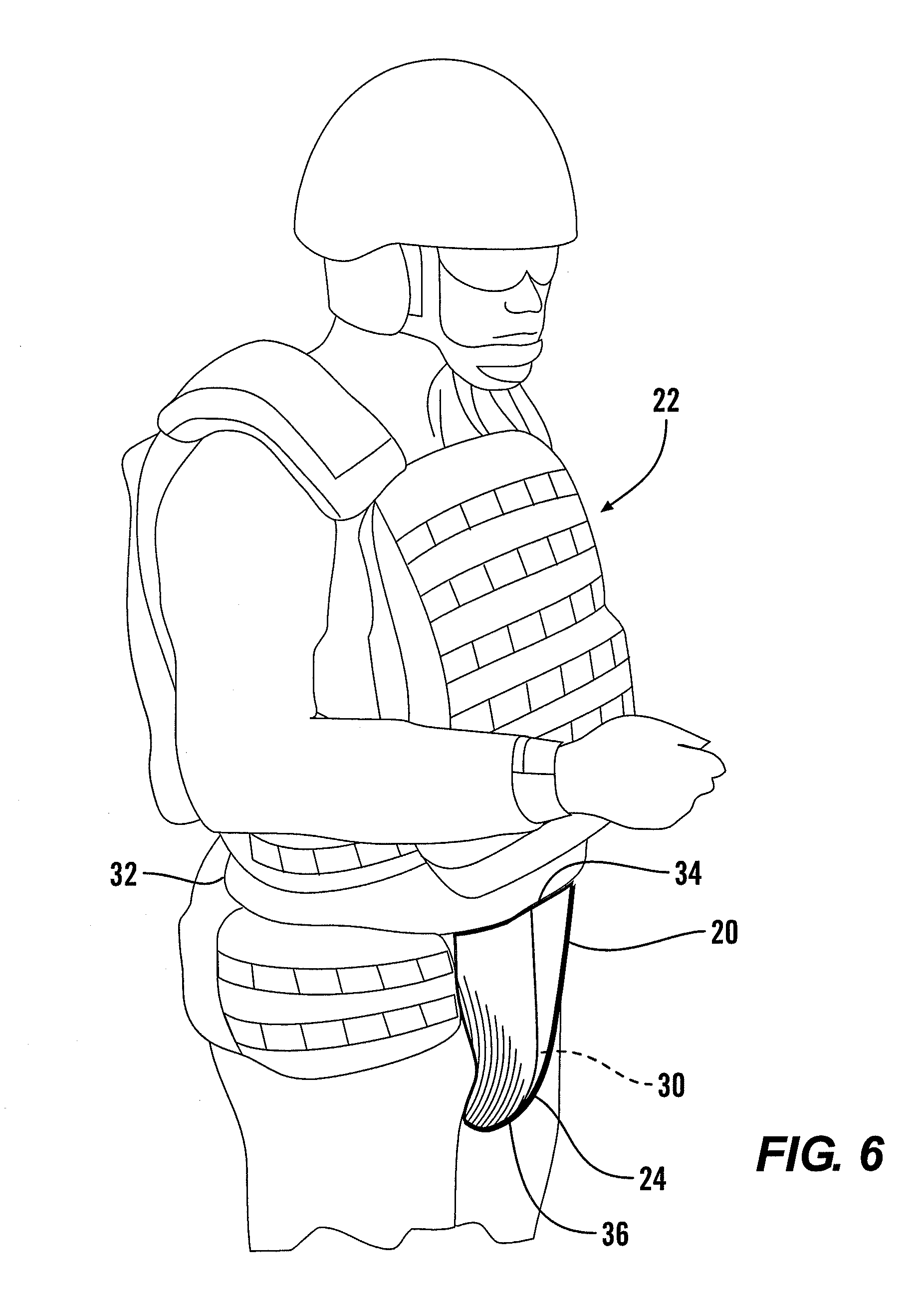
[0020]Referring more particularly to FIGS. 1-7, wherein like numbers refer to similar parts, a compliant body armor ballistic element 20 is shown in FIGS. 1-3. The component 20 will typically be worn together with some type of armored vest 22, as shown in FIG. 6. The component 20 may include a fabric bag 24 which receives a soft armor ballistic element 30, as shown in FIGS. 2 and 3 and which is a thin compound curved concave element, which may be about five-sixteenths inches thick. The enclosing sewn fabric bag 24 protects the ballistic element 30 from wear and soiling. This bag may be a lightweight nylon material. The element 30 is formed as a stack of multiple layers of ballistic material 25, for example material of Kevlar® fibers, or, for example, layers of material of Spectra® ultra high molecular weight polyethylene fibers from Honeywell. The stack is formed under heat and pressure with a resin as discussed below, and may be stitched around the periphery, in a quilted pattern, ...


PUM


Abstract

The ballistic groin protector of the present invention is preferably a compound curved sheet comprised of a stack of multiple layers of ballistic material, for example material of Kevlar® fibers, or Spectra® fiber material. The stack may be stitched around the periphery. To obtain more stiffness a more or less thick plastic stiffening shape may be formed together with the layers of ballistic material. The ballistic protective element is preferably somewhat compliant and not so stiff as to excessively interfere with movement of the wearer. The ballistic element may be enclosed within a fabric bag and suspended from a belt, and have a rearwardly opening cup shape to serve to protect the groin of a wearer.

Description

CROSS REFERENCES TO RELATED APPLICATIONS[0001]This application claims the benefit of U.S. provisional App. No. 61 / 159,065, filed Mar. 10, 2009, the disclosure of which is incorporated by reference herein.STATEMENT AS TO RIGHTS TO INVENTIONS MADE UNDER FEDERALLY SPONSORED RESEARCH AND DEVELOPMENT[0002]Not applicable.BACKGROUND OF THE INVENTION[0003]The present invention relates to ballistic protective apparel.[0004]Persons exposed to projectile threats, such as police officers and soldiers, may seek a certain level of protection by wearing armored clothing. Low velocity projectiles such as handgun rounds, fragmentation rounds from a grenade or mortar, and miscellaneous shrapnel may be countered by so-called “soft armor.” Soft armor is worn in the form of jackets, vests, etc. which are composed of assemblies of ballistic fabric such as those formed from DuPont Kevlar® fibers or of Spectra® ultra high molecular weight polyethylene fibers from Honeywell. The soft armor is often fabricat...

Claims


Application Information

Patent Timeline
Patent Type & Authority Applications(United States)
IPC IPC(8): F41H1/02
CPCF41H5/0485F41H1/02
Inventor CRYE, CALEB CLARK
Owner LINEWEIGHT
Why Eureka
Try Eureka