Attachement of a jet engine nacelle structure by means of a reinforced knife-edge/groove coupling

a jet engine and nacelle technology, applied in the direction of jet propulsion plants, aircraft power plant components, aircraft components, etc., can solve the problems of heavy and expensive, and achieve the effect of not introducing an excessive burden

Inactive Publication Date: 2010-09-16
AIRCELLE
View PDF12 Cites 8 Cited by
  • Summary
  • Abstract
  • Description
  • Claims
  • Application Information

AI Technical Summary

Benefits of technology

[0011]The invention provides a nacelle that has a rear section connected to the middle section by means of a clamp of the ...

Problems solved by technology

Producing the knife-edge using reinforcing segments means that the impact both on the mass of the whole of the clamp and on the cost thereof is not excessive, recours...

Method used


Image

  • Attachement of a jet engine nacelle structure by means of a reinforced knife-edge/groove coupling
  • Attachement of a jet engine nacelle structure by means of a reinforced knife-edge/groove coupling
  • Attachement of a jet engine nacelle structure by means of a reinforced knife-edge/groove coupling

Examples


Embodiment Construction

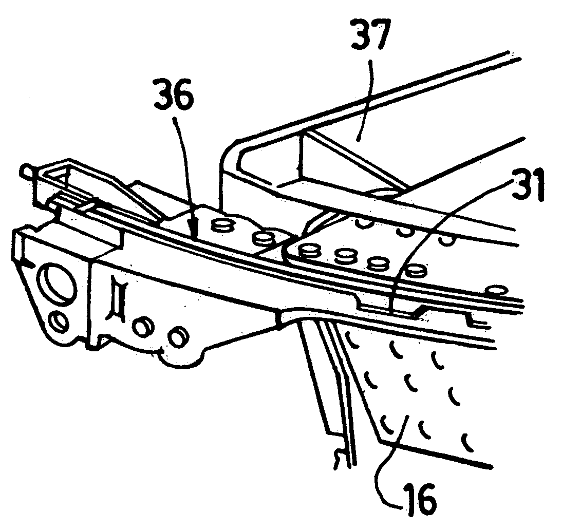
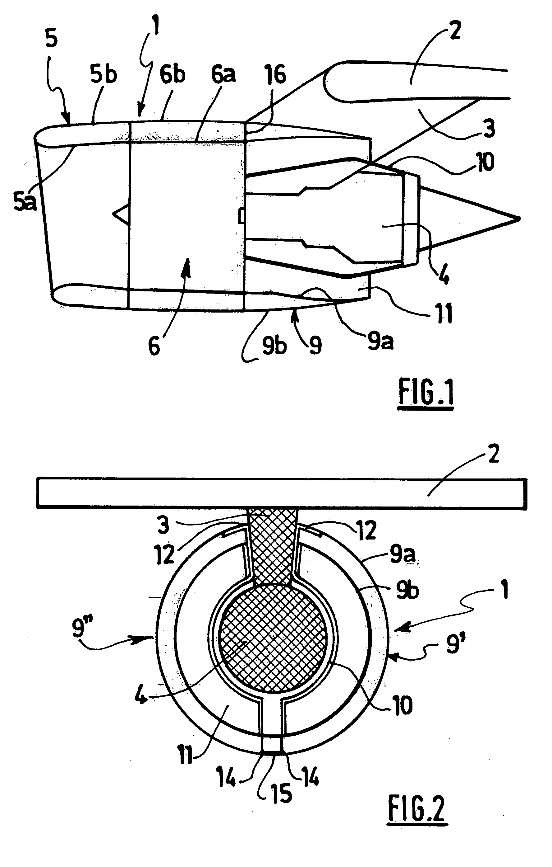
[0033]A nacelle 1 according to the invention as depicted in FIGS. 1 and 2 is intended to be attached under a wing 2 of an airplane (not visible) via an oblique pylon 3 directed toward the front of the airplane.

[0034]This nacelle 1 constitutes a tubular housing for a jet engine 1 the air flows generated by which it channels. It also houses various components needed for the operation of the jet engine 4.

[0035]More specifically, the nacelle 1 has an outer structure comprising a front section forming an air intake 5, a middle section 6 surrounding a fan 7 of the jet engine, and a rear section 9 surrounding the engine and possibly housing a thrust-reversal system (not visible).

[0036]The middle section 6 comprises, on the one hand, an inner casing 6a surrounding the fan of the jet engine 4, and, on the other hand, an outer structure 6b for cowling the casing extending an outer surface 5b of the air intake section 5. The casing 6a is attached to the air intake section 5 that it supports an...


PUM


Abstract

The present invention relates to a nacelle (1) for a jet engine (4) comprising a forward air inlet section (5), a mid-section (6) intended to surround a jet engine fan, and an aft section (9), at least one portion forming the aft section being connected to the mid-section via an at least partially peripheral radial knife-edge (31) capable of engaging by complementarity of shape with a corresponding groove (32) belonging to a portion (6a) of the mid-section, characterized in that the knife-edge comprises at least one reinforcing segment (35, 36) situated in a region for accommodating high loads, said reinforcing segment being made from a material which is stronger than the remainder of the knife-edge and tailored to the loads which are to be borne by said segment in this region.

Description

TECHNICAL FIELD[0001]The present invention relates to a nacelle for a jet engine.BACKGROUND[0002]An airplane is propelled by a number of jet engines each housed in a nacelle.[0003]A nacelle generally has a tubular structure comprising an air intake forward of the jet engine, a middle section intended to surround a fan of the jet engine, a downstream section that may incorporate thrust-reversal means and is intended to surround the combustion chamber of the jet engine, and generally ends in a jet pipe, the outlet of which is situated downstream of the jet engine.[0004]Modern nacelles are intended to house a bypass jet engine capable of generating, on the one hand, a flow of hot air (also known as the primary flow) from the jet engine combustion chamber and, on the other hand, a flow of cold air (the secondary or bypass flow) from the fan and flowing around the outside of the jet engine through an annular passage, also known as a flow path, formed between an inner structure defining a...

Claims


Application Information

Patent Timeline
IPC IPC(8): B64D29/06
CPCB64D29/06
Inventor GERMAIN, ETIENNEELEGOET, JEAN-YVESDHAINAULT, PATRICE
Owner AIRCELLE
Why Eureka
Try Eureka