Bicycle tire

a technology for bicycles and tires, applied in the field of bicycle tires, can solve the problems of tire becoming too stiff, affecting the conformation ability of tires, and affecting the performance of tires,

Inactive Publication Date: 2010-09-16
KAWAI SHUJI
View PDF1 Cites 7 Cited by
  • Summary
  • Abstract
  • Description
  • Claims
  • Application Information

AI Technical Summary

Benefits of technology

[0012]In a first aspect the present invention provides a bicycle tire including a first sidewall and a second sidewall each including an interior portion and an exterior portion. A rim attaching portion including a slipping reduction portio

Problems solved by technology

During the compression, the inner-tube is pinched between the hard edge of the wheel rim and the object causing the impact, ultimately puncturing the inner-tube and creating a flat tire.
Increasing rigidity of the tire sidewall by increasing thickness of the entire sidewall can reduce tire compression, but problems associated with this include greater overall tire weight and the tire becoming too stiff and losing ability to conform to the terrain/surface, which is necessary for better traction, and also increases cost of production and/or material.
Liners can be applied to the inside of the tire to disperse force from the concentrated area, but have a disadvantage of large cost increase.
Tubeless tire systems do not have inner-tubes to pinch, but converting a tube type of tire to a tubeless system requires the expense of new rims designed specifically for tubeless tires, and purchasing tires exclusively designed to work with tubeless rims.
The rim lip can be shaped differently to disperse force from a concentrated area, but this has a major disadvantage of increasing cost for replacing an entire rim.
The unintended separation of the bead from the rim (area 610 separating from area 130, i.e., roll-off) is shown in FIG. 6 and FIG. 8 and is highly undesirable because of the sudden l

Method used


Image

  • Bicycle tire
  • Bicycle tire
  • Bicycle tire

Examples


Embodiment Construction

[0036]The following description is made for the purpose of illustrating the general principles of the invention and is not meant to limit the inventive concepts claimed herein. Further, particular features described herein can be used in combination with other described features in each of the various possible combinations and permutations. Unless otherwise specifically defined herein, all terms are to be given their broadest possible interpretation including meanings implied from the specification as well as meanings understood by those skilled in the art and / or as defined in dictionaries, treatises, etc.

[0037]The description may disclose several preferred embodiments for tires, as well as operation and / or component parts thereof. While the following description will be described in terms of bicycle tires for clarity and to place the invention in context, it should be kept in mind that the teachings herein may have broad application to all types of tire systems, devices and applica...


PUM


Abstract

A bicycle tire provides a first sidewall and a second sidewall each including an interior portion and an exterior portion. A rim attaching portion including a slipping reduction portion having an extended rim contact surface is connected to an inner circumference of each of the first sidewall and the second sidewall. A tire tread portion is connected to an outer circumference of the first sidewall and the second sidewall.

Description

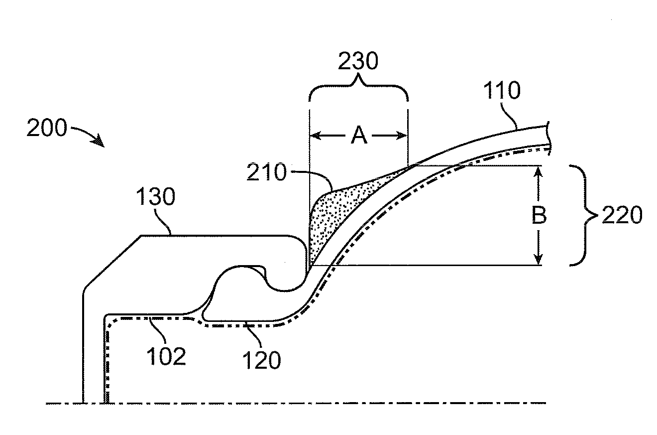
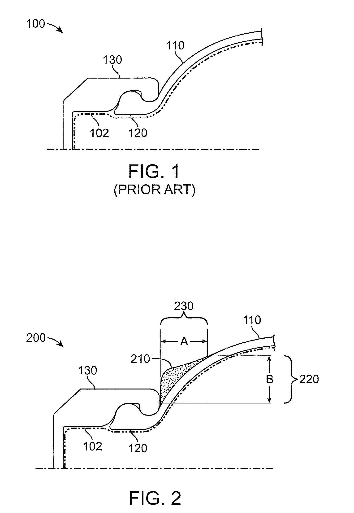
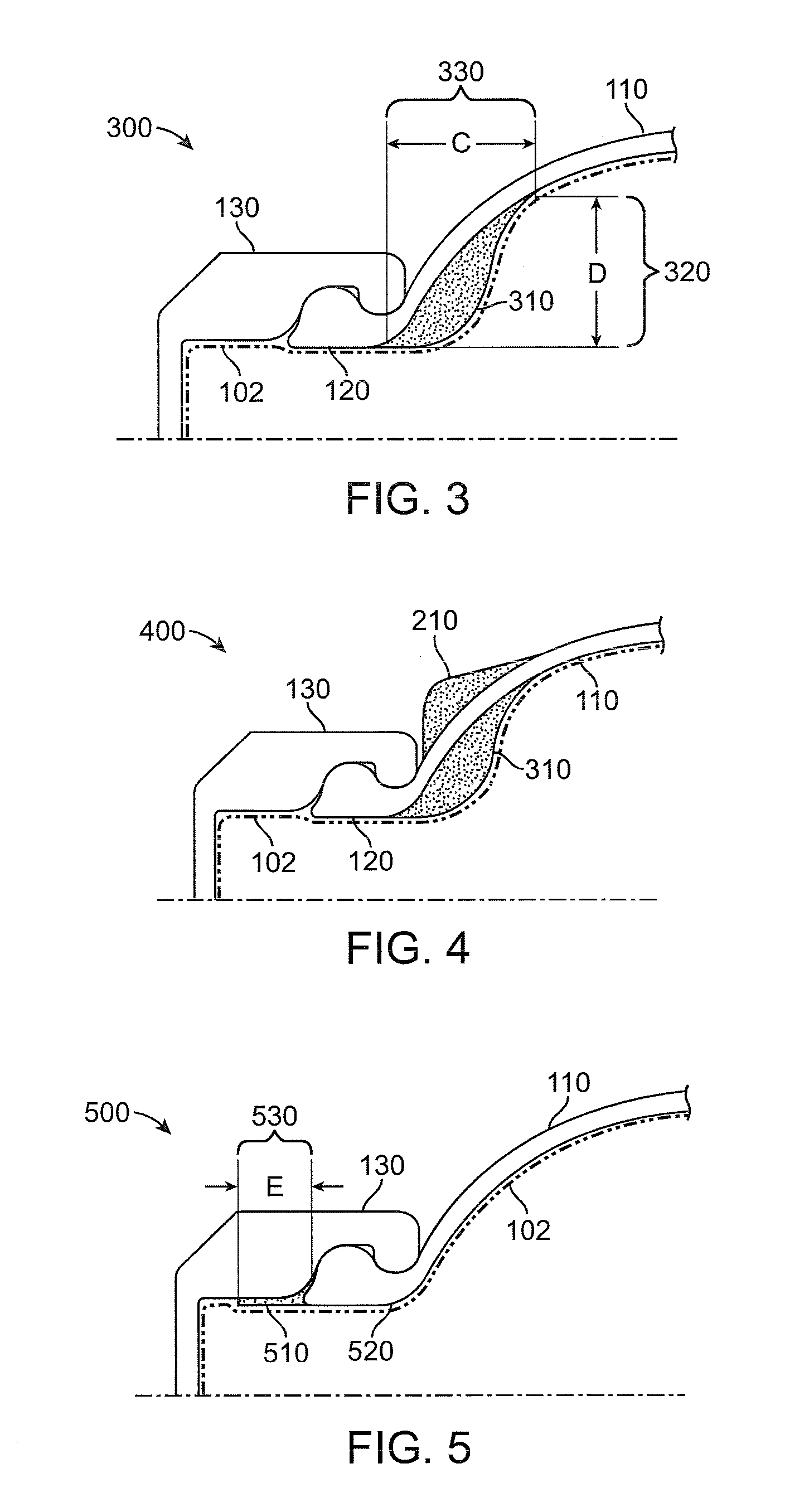
CROSS-REFERENCE TO RELATED APPLICATIONS[0001]This Non-Provisional application claims priority under 35 U.S.C. §119(e) of U.S. Provisional Application No. 61 / 159,279 filed on Mar. 11, 2009, the entire contents of which are hereby incorporated by reference.BACKGROUND[0002]1. Field of the Invention[0003]The present invention relates generally to tires. In particular, the present invention relates to bicycle tires that reduce the probability of flat tires.[0004]2. Background Information[0005]Pinch flatting of tires, such as bicycle tires, occurs when an under-inflated tire makes forceful impact with sharp objects (e.g., rocks, ledges, etc.) causing the tire to quickly compress. During the compression, the inner-tube is pinched between the hard edge of the wheel rim and the object causing the impact, ultimately puncturing the inner-tube and creating a flat tire.[0006]Increasing rigidity of the tire sidewall by increasing thickness of the entire sidewall can reduce tire compression, but p...

Claims


Application Information

Patent Timeline
IPC IPC(8): B60C5/02B60C5/12
CPCB60C5/02B60C15/024Y10T152/10657B60C17/0009B60C2200/12
Inventor KAWAI, SHUJI
Owner KAWAI SHUJI
Why Eureka
Try Eureka