
Adjustable Weighted Wheel Assembly

a wheel assembly and weight technology, applied in the direction of wheel ballasting weights, vehicle components, toys, etc., can solve the problems of difficult to change the number or type of weights, time-consuming and laborious process, and often crudely attached to the rim, so as to prevent the weight from dislodging, maintain the weight, and prevent the effect of weight dislodging

Inactive Publication Date: 2010-09-16
VANQUISH PRODS
View PDF10 Cites 15 Cited by
  • Summary
  • Abstract
  • Description
  • Claims
  • Application Information

AI Technical Summary

Benefits of technology

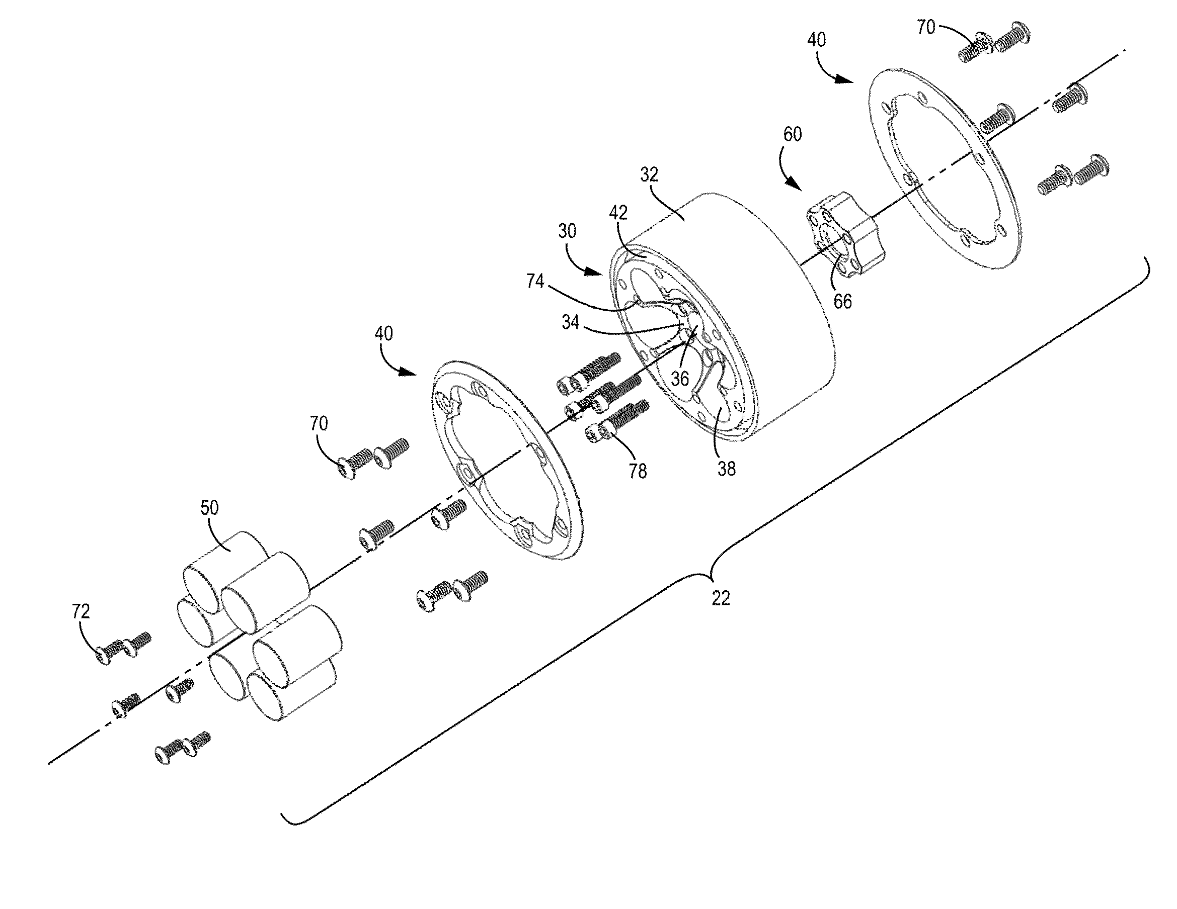
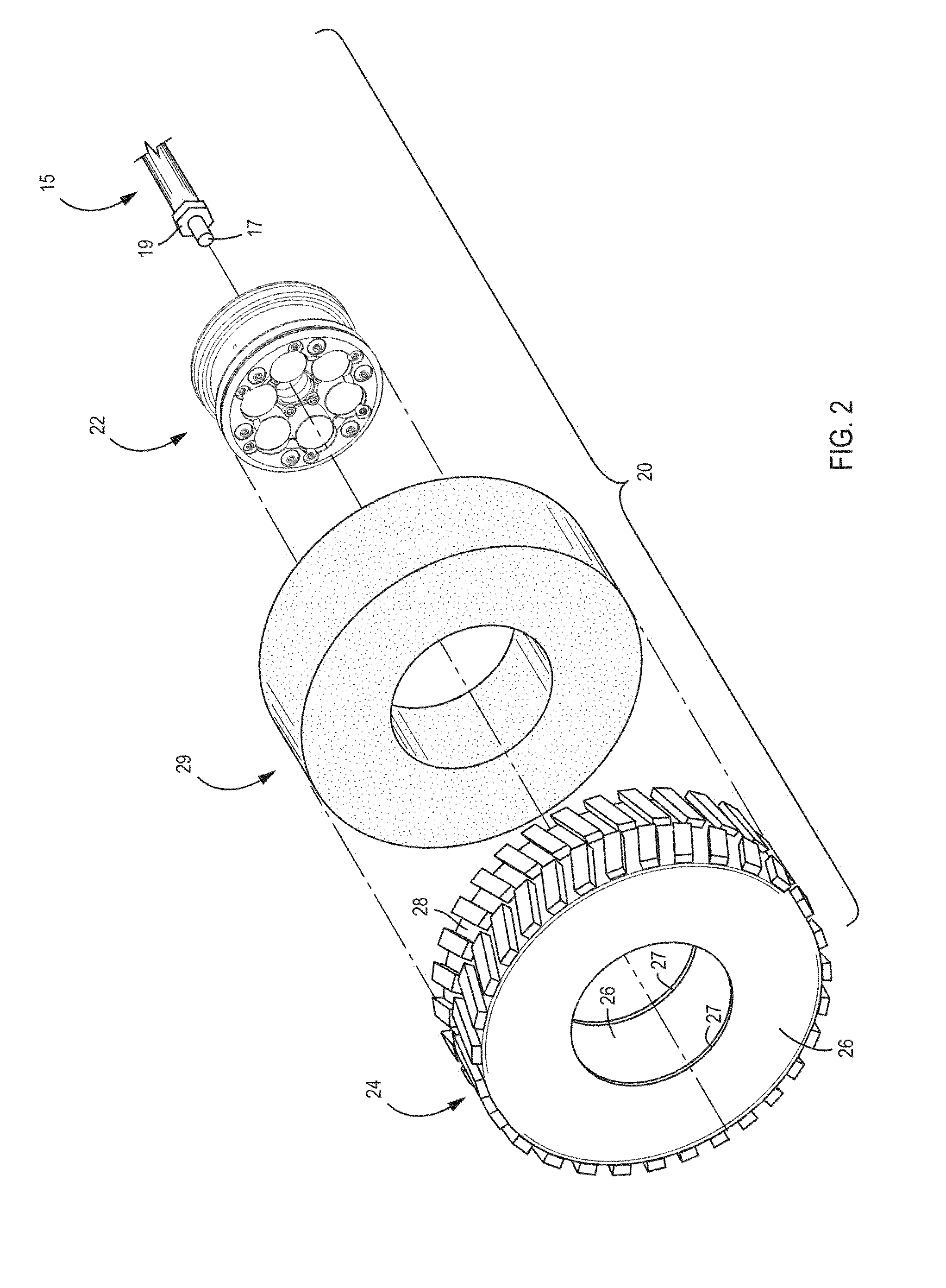
[0005]One embodiment of the present application relates to a wheel assembly comprising: a wheel comprising a main body, a substantially cylindrical wall, a front hub face and a back hub face comprising a central portion connecting a hub to an outer rim, wherein the front hub face or the back hub face comprise a socket for receiving a removable weight, wherein the socket or the weight is configured with a stop for preventing the weight from dislodging from the socket; a back hub face comprising a back central portion connecting the hub to the back outer rim; and the wheel assembly comprising at least one fastener for securing the weigh in the socket on the main body of the wheel. In one variation of the wheel assembly, the socket or the weight is configured with the stop to prevent the weight from moving in an axial direction toward the back face of the wheel. In another variation, the socket is configured with the stop to prevent the weight from moving in an axial direction toward the front face of the wheel. In one variation as used herein, the fastener may comprise of screws, O-rings, clips, spring loaded clips, brackets, magnets, etc. . . . In another variation, the weight may further comprise the “fastener” or may itself be fastened, wherein the weight may be threaded and screwed into the socket having matching threads. In one aspect of the wheel assembly, the socket comprises of at least one, two, three, four, five or six sockets for receiving a plurality of weights, and wherein the weights are secured in the sockets with at least one fastener. In another variation, the wheel assembly comprises seven, eight, nine, ten or more sockets. In a particular embodiment, the socket is a concentric socket adapted to retain a weight. The weight may comprise of one or more weights that may be inserted in the socket, and the weight may be configured in the similar or different shape, dimension and configuration as the socket. In a particular embodiment, the fastener is an O-ring coupled to the socket for securing the weight in the socket. In another aspect, the fastener is a threaded fastener. In one variation of the above, the fastener further comprises a retaining member coupled to the fastener for retaining the weight in the socket. In another aspect, the retaining member is a substantially coaxial annular member, square member or rectangular member where at least a portion of the retaining member overlaps with the socket opening to retain the weight. In another aspect, the wheel assembly comprises at least one fastener for retaining the weight in the socket. In yet another aspect, the fastener is a spring loaded retainer that retains the weight in the socket. In a particular aspect of the above, the fastener comprises a spring loaded retainer comprising an engaging element and a biasing member for retaining the weight in the socket. In another aspect, the cylindrical wall further comprises a through hole allowing air to pass through. In one variation, the through hole is coupled with an adjustable air release valve for regulating the flow of air through the through hole. In another aspect, the fastener comprises a quick-change threaded faster coupled with a retain...

Problems solved by technology

Further, such weights are often crudely attached to the rim, such as with tape.
Using such weights, therefore, represents a time consuming and involved process.
Additionally, it is also difficult to change the number or types of weights, requiring the complete removal and re-taping of the weights, along with the removal of the tire.

Method used


Image

  • Adjustable Weighted Wheel Assembly
  • Adjustable Weighted Wheel Assembly
  • Adjustable Weighted Wheel Assembly

Examples


Embodiment Construction

[0022]The invention is described in more detail hereinafter with reference to exemplary embodiments. In the figures, for the sake of clarity, the same reference numerals are used for similar components in different embodiments.

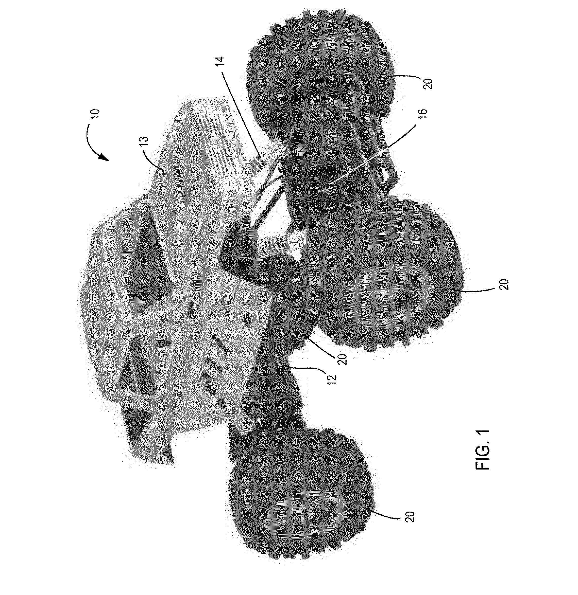
[0023]Referring to FIG. 1, a radio controlled model vehicle 10 is shown according to an exemplary embodiment. The vehicle 10 is configured to be controlled via radio waves from a handheld controller. The vehicle 10 preferably comprises a substantially chassis or frame 12. An aerodynamically shaped shell or body 13. The body 13 may include a multitude of vehicular detailing. The detailing may be three dimensional merely surface ornamentation or indicia. Such detailing may be functional or may simply simulate similar functional elements on larger vehicles.

[0024]The frame 12 is coupled to a multitude of wheels 20 (generally four) with a suspension 14. According to one embodiment, each of the wheels 20 has a suspension 14. One or more motors 16 provide power to th...


PUM


Abstract

The application discloses a wheel assembly comprising a wheel comprising a main body, a substantially cylindrical wall, a front hub face comprising a central portion connecting a hub to an outer rim, wherein the front hub face comprises a socket for receiving a removable weight, wherein the socket or the weight is configured with a stop for preventing the weight from dislodging from the socket; a back face comprising a back central portion connecting the hub to the back outer rim; and the wheel assembly comprising at least one fastener for securing the weigh in the socket on the main body of the wheel.

Description

RELATED APPLICATION[0001]This application claims the benefit of U.S. Provisional Application No. 61 / 159,057, filed Mar. 10, 2009, which is incorporated herein by reference.BACKGROUND OF THE INVENTION[0002]The present disclosure relates generally to the field of weighted wheel assembly for vehicle, such as wheel assembly for radio controlled (RC) model vehicles. More specifically, the disclosure relates to adjustable and removable weights for wheels for an RC vehicle that may be used for rock crawling.[0003]Some RC vehicles are designed for rock crawling, requiring navigation over obstacles and extremely uneven, rocky surfaces. Such vehicles are often driven up steep slopes, sometimes approaching a vertical orientation. To maintain stability and reduce the likelihood that the vehicle will tip over, rock crawling vehicles are generally designed with a low center of gravity. RC rock crawling vehicles may have their centers of gravity further lowered by weighting the wheels. Wheels for ...

Claims


Application Information

Patent Timeline
IPC IPC(8): A63H17/26B60B15/28
CPCB60B15/28A63H17/262
Inventor EATON, JAMES A.
Owner VANQUISH PRODS
Learn More