
Dry cell holder and flashlight having the same

a technology of dry cell holder and flashlight, which is applied in the direction of cell components, lighting and heating apparatus, cell component details, etc., can solve the problems of unfavorable carrying of flashlight, damage to screwed portions and inability to manufacture the front plate, rear plate and supporting plate of cylindrical dry cell holder once by, etc., to achieve good appearance, light weight, and high quality

Inactive Publication Date: 2010-09-16
AITEC
View PDF1 Cites 67 Cited by
  • Summary
  • Abstract
  • Description
  • Claims
  • Application Information

AI Technical Summary

Benefits of technology

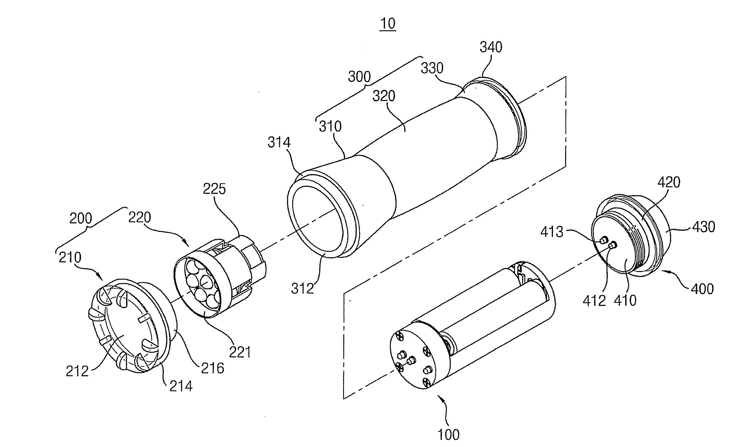
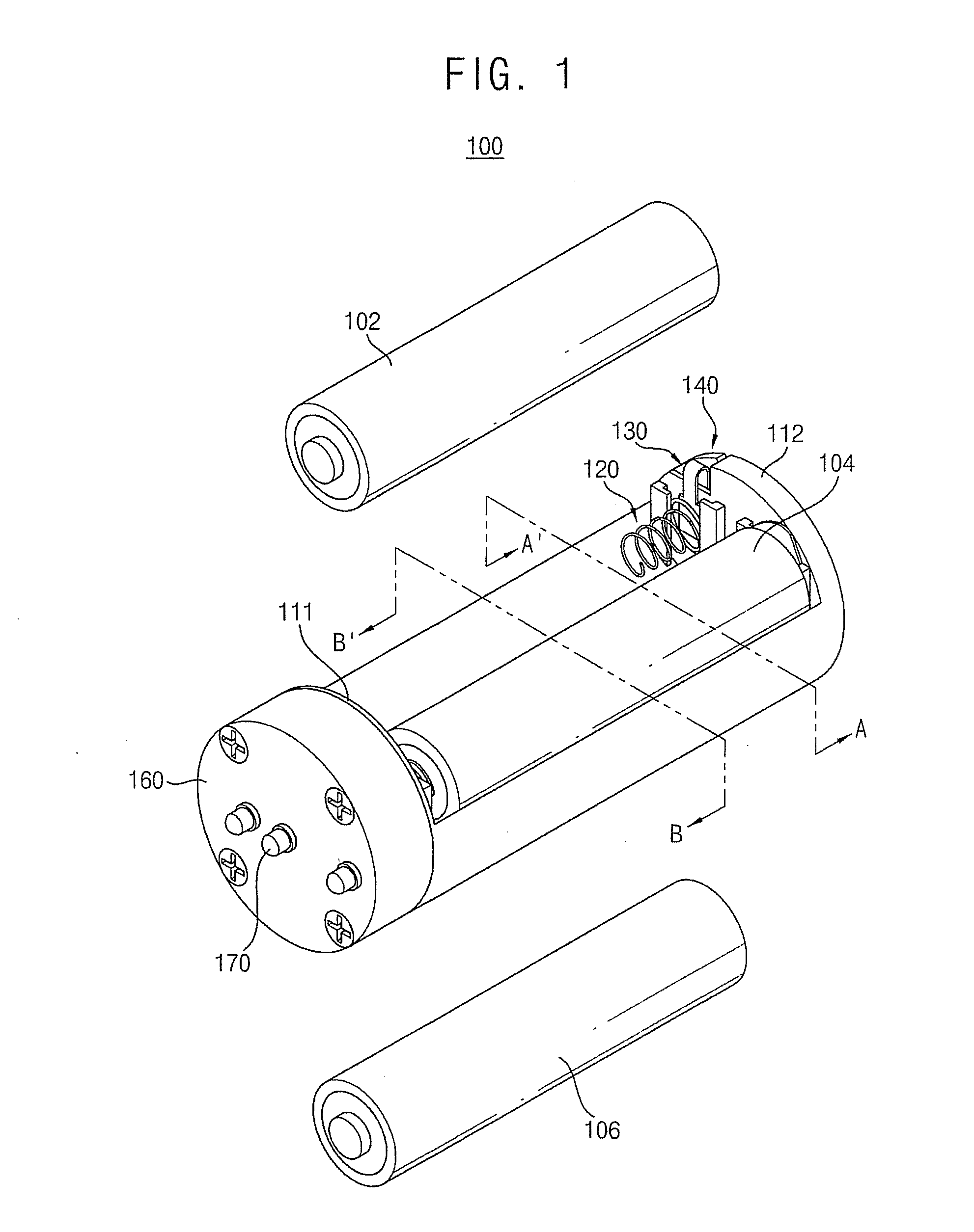
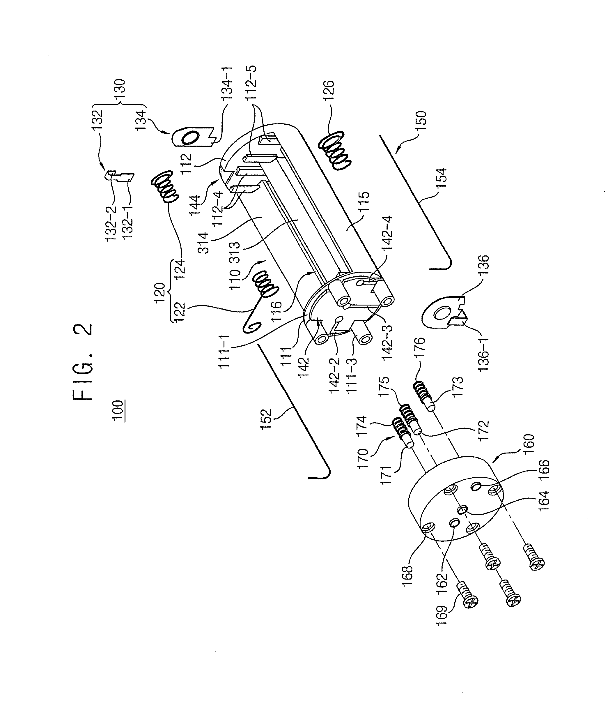
[0012]Example embodiments provide a dry cell holder having a function of transmitting switching signals to a front lamp irrespective of a body or a cable, a strong strength against damage and a light weight and giving an improved grip feeling.
[0020]According to some example embodiments, a rear switching signal may be transmitted to the head through the dry cell holder, so that the flashlight may have various displays and high quality. Further, because a current path through the body may not be required, the body may include a nonconductor such as wood, plastic, etc., so that the flashlight may have a light weight and good appearance. Furthermore, the dry cell holder may have one body including the front plate, the rear plate and the supporting plate by the injection molding, so that the dry cell holder may have improved durability.

Problems solved by technology

This flashlight may be uneasy to carry.
Therefore, a front plate, a rear plate and a supporting plate of the cylindrical dry cell holder may not be manufactured once by an injection molding.
Screwed portions of the cylindrical dry cell holder may be damaged.
Further, when the screws become loose, a contact fail between the dry cell and a terminal in the cylindrical dry cell holder may be generated.
Furthermore, when the cylindrical dry cell holder or the flashlight is dropped, the cylindrical dry cell holder may be disassembled or broken.
As a result, displays of various lamp signals may be limited.

Method used


Image

  • Dry cell holder and flashlight having the same
  • Dry cell holder and flashlight having the same
  • Dry cell holder and flashlight having the same

Examples


Embodiment Construction

[0044]Various example embodiments will be described more fully hereinafter with reference to the accompanying drawings, in which some example embodiments are shown. The present invention may, however, be embodied in many different forms and should not be construed as limited to the example embodiments set forth herein. Rather, these example embodiments are provided so that this disclosure will be thorough and complete, and will fully convey the scope of the present invention to those skilled in the art. In the drawings, the sizes and relative sizes of layers and regions may be exaggerated for clarity.

[0045]It will be understood that when an element or layer is referred to as being “on,”“connected to” or “coupled to” another element or layer, it can be directly on, connected or coupled to the other element or layer or intervening elements or layers may be present. In contrast, when an element is referred to as being “directly on,”“directly connected to” or “directly coupled to” anoth...


PUM

PropertyMeasurementUnit
diameteraaaaaaaaaa
lengthaaaaaaaaaa
lengthaaaaaaaaaa

Abstract

A dry cell holder may include a cylindrical body, an anode terminal, a cathode terminal, a switching signal terminal, a first electrode terminal and a second electrode terminal. The cylindrical body may have a front plate and a rear plate. The anode terminal may be formed on the front plate. The cathode terminal may be formed on the front plate. The switching signal terminal may be formed on the front plate. The first electrode terminal may be formed on the rear plate. The first electrode terminal may be connected to the anode terminal. The first electrode terminal may be connected to the cathode terminal. The second electrode terminal may be formed on the rear plate. The second electrode terminal may be connected to the switching signal terminal.

Description

CROSS-RELATED APPLICATION[0001]This application claims priority under 35 USC §119 to Korean Patent Application No. 2009-20106, filed on Mar. 10, 2009 in the Korean Intellectual Property Office (KIPO), the contents of which are herein incorporated by reference in their entirety.BACKGROUND[0002]1. Field[0003]Example embodiments relate to a dry cell holder and a flashlight having the same. More particularly, example embodiments relate to a cylindrical dry cell holder configured to receive three AAA dry cells, and a flashlight having the dry cell holder.[0004]2. Description of the Related Art[0005]Generally, a flashlight may include a lamp, a dry cell, a switch and a case. The lamp, the dry cell and the switch may be received in the case. The case may have a cylindrical shape for allowing a user to easily carry and hold with a hand.[0006]Recently, the lamp may be converted into a light emitting diode (LED) having low power consumption from a filament bulb. Thus, the dry cell may also be...

Claims


Application Information

Patent Timeline
Patent Type & Authority Applications(United States)
IPC IPC(8): H05B39/00H01M2/10F21L4/02
CPCF21L4/027F21V14/065F21V23/0414H05B33/0845F21Y2101/02H01M2/105F21V23/0421F21Y2115/10F21Y2115/30H05B45/10H01M50/213Y02E60/10F21L4/08F21V17/10
Inventor YOON, SANG-YEON
Owner AITEC
Learn More