Liquid ejecting apparatus

a technology of liquid ejector and ejector, which is applied in the direction of printing, etc., can solve the problems of printing error and dot omission

Inactive Publication Date: 2010-09-16
SEIKO EPSON CORP
View PDF7 Cites 12 Cited by
  • Summary
  • Abstract
  • Description
  • Claims
  • Application Information

AI Technical Summary

Benefits of technology

[0016]With such a configuration, in the state where the first pressure control chamber is sealed to be depressurized, the suction mechanism is connected to the ejection port, and then the first pressure control chamber is made to be in the first communication state. Accordingly, it is possible to displace the first partition wall portion toward the liquid storing chamber, and to decrease a force of the liquid located on the downstream side of the pressure control valve and applied to the first pressure control chamber. As a result, it is possible to allow the liquid on the downstream side of the pressure control valve to vigorously flow toward the ejection port by using the displacement of the first partition wall portion and the suction force of the ejection port, and thus to discharge a large amount of liquid or bubbles remaining in the ejection port.

Problems solved by technology

In the technology using the pressure control valve, since the structure of the pressure control valve is complex, bubbles contained in ink easily stay in the vicinity of the pressure control valve.
For this reason, in the case where the bubbles stay without performing the printing operation for some time, the bubbles grow, and hence large bubbles may exist in the ink storing chamber.
In this case, the large bubbles may flow into the nozzles together with ink during a printing operation, and may cause a printing error such as a dot omission.
In addition, the above-described problem may arise in a liquid ejecting apparatus for ejecting an arbitrary liquid such as lubricant or resin liquid as well as the ink jet printer.

Method used


Image

  • Liquid ejecting apparatus
  • Liquid ejecting apparatus
  • Liquid ejecting apparatus

Examples


first embodiment

A. FIRST EMBODIMENT

A1. Configuration of Apparatus

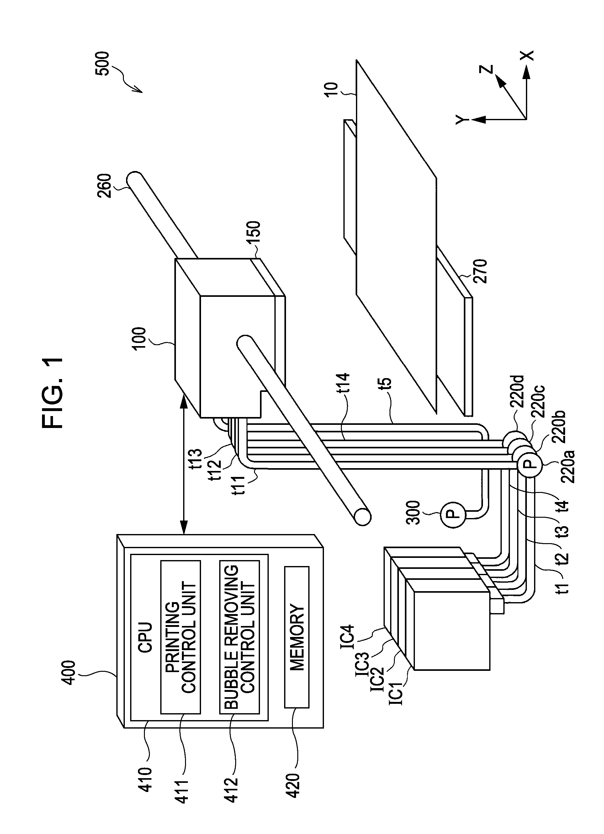
[0026]FIG. 1 is an explanatory diagram illustrating a schematic configuration of a printer 500 including a carriage 100 as a bubble removing mechanism according to the invention. The printer 500 is an ink jet printer capable of ejecting four colors (black, cyan, magenta, and yellow) of ink. The printer 500 includes an ink cartridge IC1 of black ink, an ink cartridge IC2 of cyan ink, an ink cartridge IC3 of magenta ink, an ink cartridge IC4 of yellow ink, the carriage 100, a printing head 150, four ink supply pumps 220a, 220b, 220c, and 220d, a depressurizing pump 300, a guide rod 260, a platen 270, and a control substrate 400.

[0027]The printer 500 is a so-called off-carriage type printer in which four ink cartridges IC1 to IC4 are attached to a printer body. The ink cartridge IC1 is connected to the carriage 100 through a tube t1, the ink supply pump 220a, and a tube t11. In the same manner, the ink cartridge IC2 is connected to the c...

second embodiment

B. SECOND EMBODIMENT

[0053]FIG. 5 is an explanatory diagram illustrating a schematic configuration of a printer according to a second embodiment. FIG. 6 is a flowchart illustrating a sequence of a bubble removing process according to the second embodiment.

[0054]A printer 500a according to the second embodiment has the same configuration as that of the printer 500 (FIGS. 1 to FIGS. 4A and 4B) according to the first embodiment except that a suction recovery cap 450 and a suction recovery pump 452 are provided, and Step S125 and Step S130 are further performed in the bubble removing process.

[0055]The suction recovery cap 450 (FIG. 5) is disposed at a home position of the carriage 100, and is used to receive the ink discharged from the printing head 150 while capping the lower portion of the printing head 150. An ink absorber (not shown) such as a urethane foam is disposed inside the printing head 150, and the ink discharged from the printing head 150 is absorbed by the ink absorber. In ...

third embodiment

C. THIRD EMBODIMENT

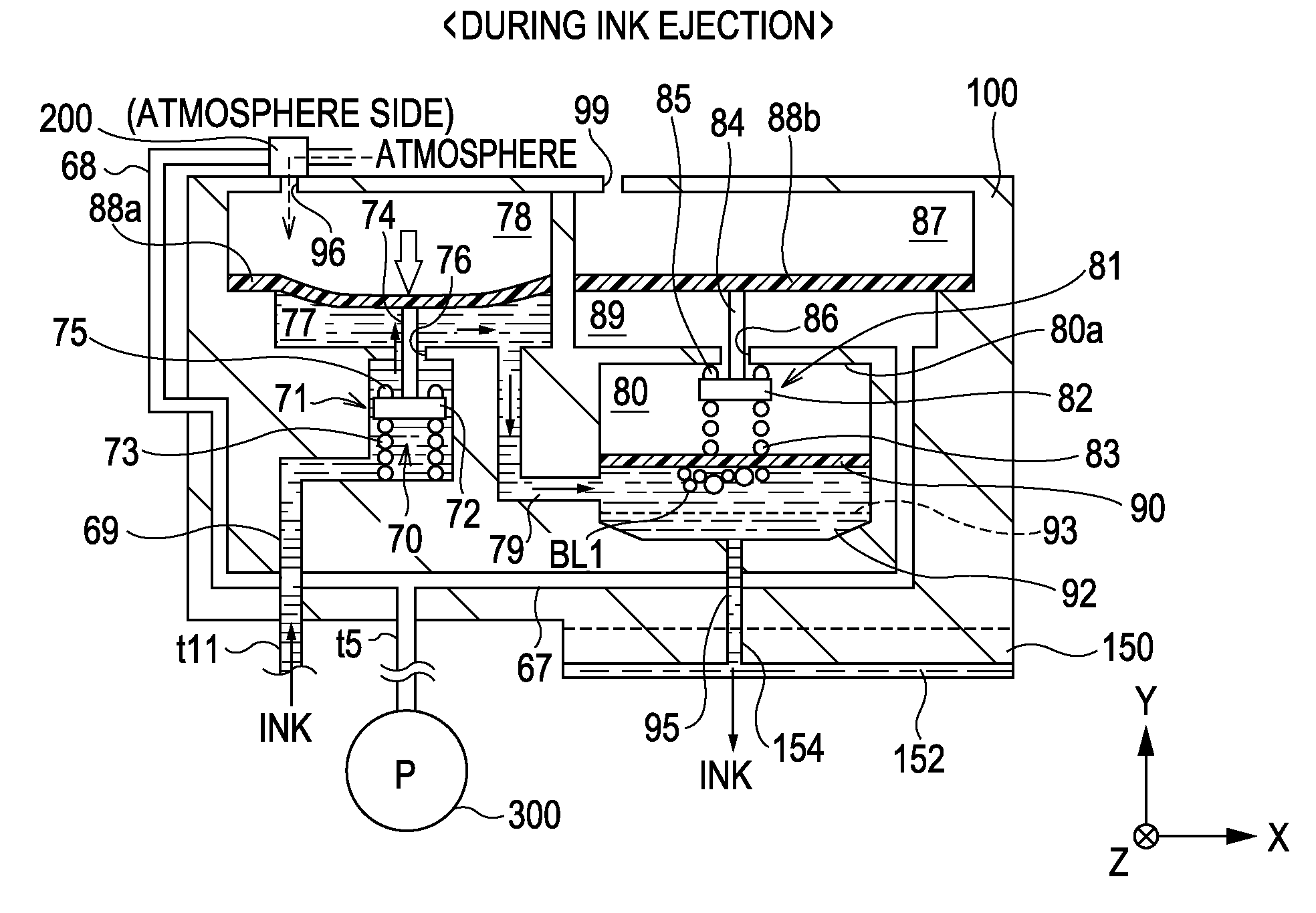
[0061]FIG. 8 is an explanatory diagram schematically illustrating the sections of the carriage 100 and the printing head 150 according to a third embodiment. A printer (not shown) according to the third embodiment has the same configuration as that of the printer 500 (FIGS. 1 to 4A and 4B) according to the first embodiment except that an exclusive second depressurizing pump 301 is provided so as to depressurize the first atmosphere chamber 78.

[0062]The second depressurizing pump 301 is connected to the switching valve 200 through the negative pressure supply path 68. The second depressurizing pump 301 is controlled by the bubble removing control unit 412 as in the depressurizing pump 300 (simply referred to as a first depressurizing pump). In addition, in the third embodiment, the first depressurizing pump 300 is used as a pump exclusively depressurizing the depressurizing chamber 80.

[0063]The printer according to the third embodiment having the above-described co...


PUM


Abstract

Provided is a liquid ejecting apparatus for ejecting a liquid, including: a depressurizing pump: a liquid storing chamber which includes an inlet for the liquid and stores the liquid; a first partition wall portion which has flexibility and gas permeability; a first pressure control chamber which is adjacent to the liquid storing chamber with the first partition wall portion interposed therebetween; a pressure control valve which opens or seals the inlet in response to displacement of the first partition wall portion; and a switching valve which is connected to the first pressure control chamber and the depressurizing pump and selects an arbitrary state among a first communication state where the first pressure control chamber communicates with an atmosphere, a second communication state where the first pressure control chamber communicates with the depressurizing pump, and a sealed state where the first pressure control chamber is sealed.

Description

[0001]This application claims the benefit of Japanese Patent Application No. 2009-057817, filed Mar. 11, 2009, which is expressly incorporated herein by reference in its entirety.BACKGROUND[0002]1. Technical Field[0003]The present invention relates to a technology of removing bubbles from a liquid flowing in a liquid ejecting apparatus.[0004]2. Related Art[0005]In an ink jet printer of an off-carriage type in which an ink cartridge is mounted to a printer body, in the case where a layout is adopted in which a head (nozzle plate) is disposed at a position lower than the ink cartridge, it is necessary to suppress a leakage of ink from nozzles due to a water head difference. Here, there is proposed a printer which suppresses an ink leakage by depressurizing an ink channel inside a head and supplies a corresponding amount of ink to be ejected to the head when ink is ejected from a nozzle. For example, JP-A-2005-186344 proposes a printer in which an ink storing chamber is provided in a h...

Claims


Application Information

Patent Timeline
Patent Type & Authority Applications(United States)
IPC IPC(8): B41J2/19
CPCB41J2/17596B41J2/17509
Inventor ITO, HIROYUKI
Owner SEIKO EPSON CORP
Why Eureka
Try Eureka