Lens Assembly Apparatus And Method

a technology of assembly apparatus and lens, applied in the field of optical apparatuses, can solve the problems of unreliability of the previous approach, difficult to achieve miniaturization, and bulky components

Inactive Publication Date: 2010-09-16
KNOWLES ELECTRONICS INC +1
View PDF9 Cites 90 Cited by
  • Summary
  • Abstract
  • Description
  • Claims
  • Application Information

AI Technical Summary

Problems solved by technology

While various types of lens systems have been employed in various applications, these previous systems suffered from several disadvantages.
Unfortunately, previous systems had components that were bulky and miniaturization became difficult to accomplish.
Unfortunately, these moving parts had a tendency to break requiring the replacement of system components and leading to the unreliability of these previous approaches.
These systems also utilized a large number of parts and this also added to the unreliability (and cost) of these approaches.
For all these reasons, previous systems were costly to produce and user satisfaction with these systems was often negatively impacted by the above-mentioned disadvantages.

Method used


Image

  • Lens Assembly Apparatus And Method
  • Lens Assembly Apparatus And Method
  • Lens Assembly Apparatus And Method

Examples


Embodiment Construction

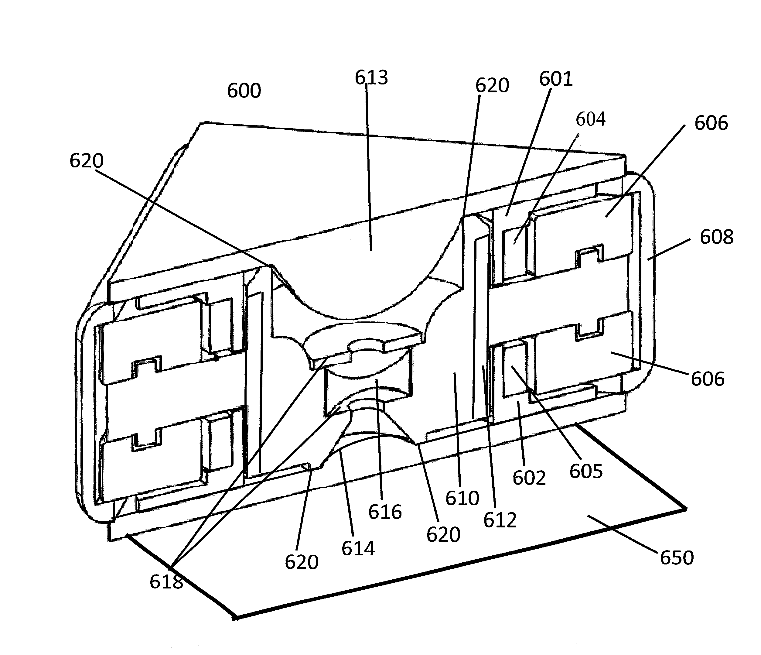
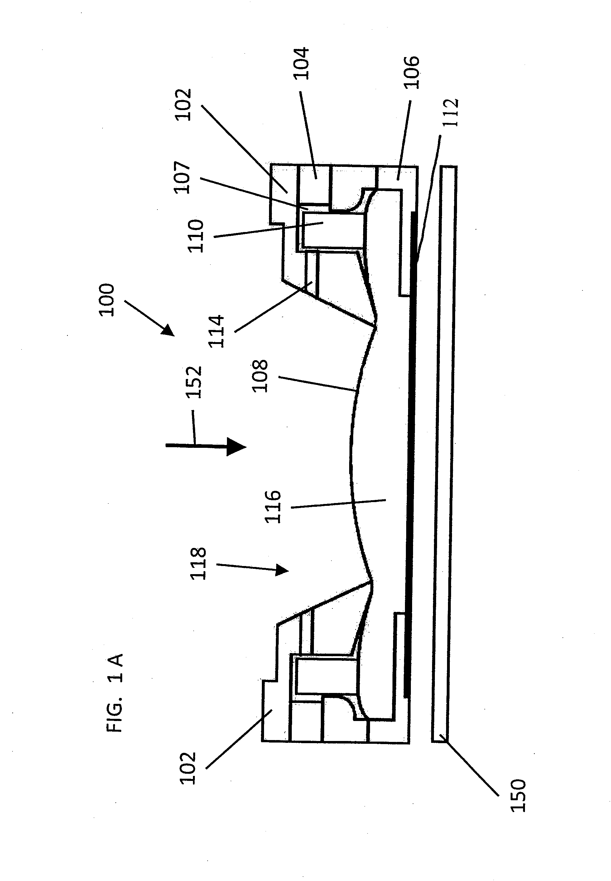
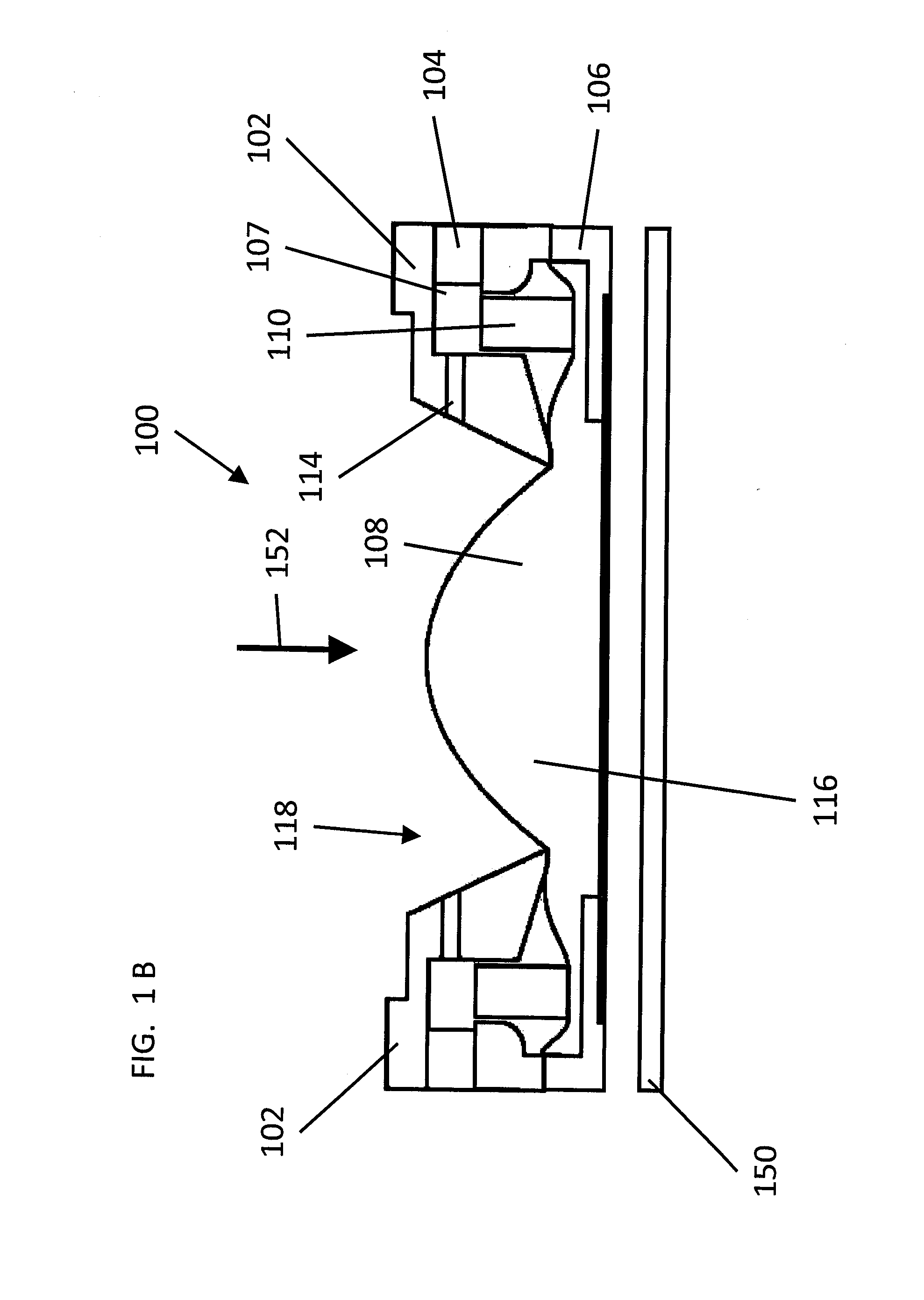
[0073]Many of the present approaches provide a magnetic lens assembly that includes a magnetic-coil actuator (e.g., a voice coil motor) which deforms one or more membranes (e.g., a polymeric membrane) in the lens assembly. Other devices such as piezo electric devices could also be used. In many of these examples, the membrane may define at least partially one or more reservoirs that are filled with a filler material (e.g., liquid, gel, or polymer). The membrane, filler material, and a container opposite the membrane, may provide a lens. It should be noted that the term “lens” should be interpreted, in most if not all of the following embodiments—as applicable—as “a three dimensional space filled with a filler material and communicating with a reservoir.” The resulting deformation of the membrane occurs via pressure provided from movement of the filler material (e.g., optical fluid) within the reservoir. Deformation of the lens alters the optical characteristics of the lens as desire...


PUM


Abstract

An optical apparatus includes a first membrane, a second membrane and at least one electromagnetically displaceable component. The first membrane includes an optically active area. The first membrane and the second membrane are coupled by a filler material disposed in a reservoir. At least one electromagnetically displaceable component is coupled to the filler material via the second membrane, such that a displacement of the at least one electromagnetically displaceable component is operative to cause a deformation of the optically active area of the first membrane by movement of the filler material.

Description

CROSS REFERENCES TO RELATED APPLICATIONS[0001]This patent claims benefit under 35 U.S.C. §119 (e) to U.S. Provisional Application No. 61 / 160,041 entitled “Lens Assembly System and Method” filed Mar. 13, 2009 having attorney docket number PO9007 and U.S. Provisional Application No. 61 / 245,438 entitled “Lens Assembly Apparatus and Method of Operation” filed Sep. 24, 2009 having attorney docket number PO9010 the contents of both of which are incorporated herein by reference in their entireties.TECHNICAL FIELD[0002]This patent relates to optical apparatuses which incorporate lenses and methods of operating lenses.BACKGROUND OF THE INVENTION[0003]Various optical lens systems have been used over the years for different purposes. For instance, some lens systems provide for magnification of an image while other lens systems provide for zooming in on an image. Lens systems can also be used for various applications and / or in different environments. For example, a lens system may be part of a ...

Claims


Application Information

Patent Timeline
Patent Type & Authority Applications(United States)
IPC IPC(8): G02B3/14G02B3/12F21V13/04
CPCG02B3/14G02B7/04G02B7/182G02B7/10H04N5/2254H04N5/2328G02B26/0825G02B27/0075G02B26/002G02B26/004H04N23/55H04N23/685
Inventor ASCHWANDEN, MANUELNIEDERER, DAVIDSCHMIDHAUSLER, THOMASROMER, CHRISTOPHKERN, THOMASYANG, SHU-HENGKING, CHARLESKIRCHHOEFER, DENNIS RAYWARREN, DANIEL
Owner KNOWLES ELECTRONICS INC
Why Eureka
Try Eureka