
Method of determining an image distribution for a light field data structure

a light field data and distribution method technology, applied in the field of determining the distribution of images for light field data structures, can solve the problems of loss of image quality, state-of-the-art techniques of light-field data compression, and inability to adapt to such considerations, and achieves the effects of low computational effort, high quality, and low cos

Inactive Publication Date: 2010-09-16
DYNAMIC DATA TECH LLC
View PDF12 Cites 4 Cited by
  • Summary
  • Abstract
  • Description
  • Claims
  • Application Information

AI Technical Summary

Benefits of technology

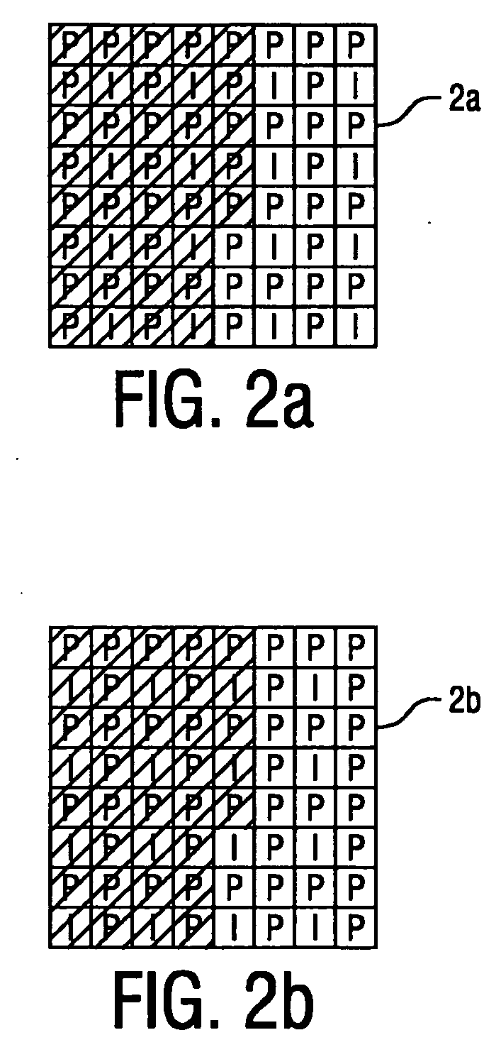
[0010]An obvious advantage of the method according to the invention is that a high level of quality for a future interactive application can be obtained with relatively little computational effort and without any additional storage or transmission requirements. With the method according to the invention, as many images as possible containing a “relevant object” are coded to a high level of quality for each of a sequence of light-field data structures that are used at a later stage in rendering three-dimensional scenes. There can be any number of predefined reference image distributions available to which the image-related array can be compared. In each comparison, the most suitable reference image distribution is chosen, so that, for each light-field data structure, as many images as possible containing the relevant object are coded as high-quality intraimages, or I-images.

Problems solved by technology

This leads to the problem of storage or transmission for the large number of images, since storage space and transmission bandwidth are expensive resources.
To store or transmit the images in a cost-effective way, the images can be compressed using some method of lossy data compression, which results in a loss of image quality that is, however, not noticeable to the viewer.
However, even more bandwidth can be saved by making use of the fact that picture data in a sequence of images is often redundant.
However, state-of-the-art techniques of light-field data compression do not adapt to such considerations.
Therefore, an ‘unfavourable’ compression scheme, in which the important object is not coded using a sufficient number of I-images, might lead to a noticeable deficiency in the quality of the rendered scenes.

Method used


Image

  • Method of determining an image distribution for a light field data structure
  • Method of determining an image distribution for a light field data structure
  • Method of determining an image distribution for a light field data structure

Examples


Embodiment Construction

[0031]In the diagrams, like numbers refer to like objects throughout. Objects in the diagrams are not necessarily drawn to scale.

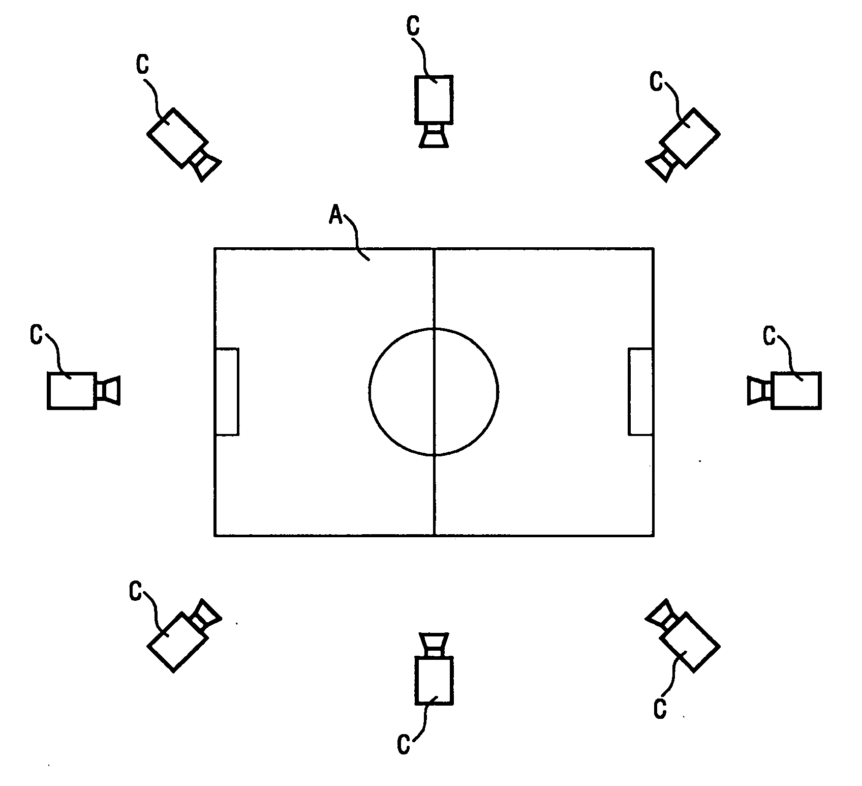
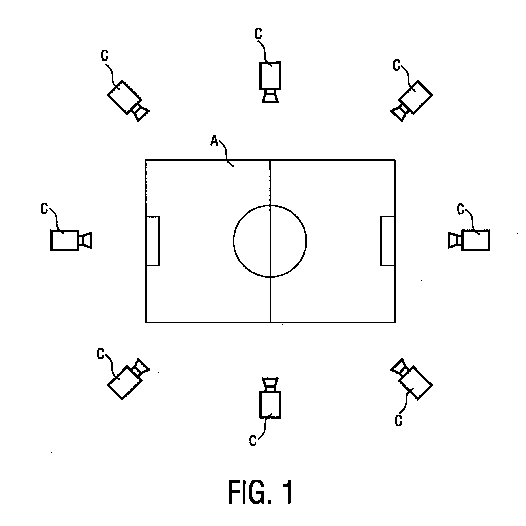
[0032]FIG. 1 shows, in a schematic representation, one type of camera arrangement for the purpose of collecting or capturing images for a three-dimensional video application. Here, the cameras are arranged about a scene. As already mentioned in the introduction, only a few cameras are shown here. In reality, a much greater number of cameras would be implemented to collect images for obtaining light-field data structures. Images captured by the cameras are combined as described above to give a sequence of light-field data structures which can be used at a later point in time to render the scene from different points of view.

[0033]Images are ideally captured by the cameras in a synchronised manner. For example, sixty-four images captured at a single instant by an arrangement of sixty-four cameras can be arranged virtually as an 8×8 array. After compression o...


PUM


Abstract

The invention relates to a method of determining an image distribution (Dopt) for a light field data structure, which method comprises obtaining a plurality of images (F1, F2, . . . , Fn) from a plurality of image sources (C1, C2, . . . , Cn), performing image analysis on each image (F1, F2, . . . , Fn) of the plurality of images (F1, F2, . . . , Fn) to determine whether a specified criterion is satisfied by the content of that image (F1, F2, . . . , Fn), and identifying a group (12) of images (F1, F2, . . . , Fn) whose contents satisfy the specified criterion. The image group (12) is compared to each reference image distribution (D1, D2, . . . , Dm) of a set of predefined reference image distributions (D1, D2, . . . , Dm,) to select an optimal image distribution (Dopt), wherein a reference image distribution (D1, D2, . . . , Dm) comprises a predefined arrangement of I-images and P-images of the light field data structure. Each image (F1, F2, . . . , Fn) of the plurality of images (F1, F2, . . . , Fn) of the light field data structure is subsequently designated to be either an I-image or a P-image according to the selected image distribution (Dopt). The invention also describes a system (1) for determining an image distribution (Dopt) for a light field data structure.

Description

FIELD OF THE INVENTION[0001]The invention relates to a method of determining an image distribution for a light field data structure. The invention further relates to a system for determining a image distribution for a light field data structure.BACKGROUND OF THE INVENTION[0002]Light-field rendering has gained in importance in recent years with continuing advances in the field of image processing and computer graphics. With light field rendering, photo-realistic views of scenes can be created using previously digitised images, whether these images have been artificially created or are images of actual scenes, captured by a camera. For instance, a light field can be generated from a three-dimensional model of a scene, or can be created using images of an actual scene, for example, images taken by an arrangement of cameras positioned about the scene. All the images of a scene, taken at a single instant, are collectively referred to as a ‘light-field data structure’. A description of li...

Claims


Application Information

Patent Timeline
Patent Type & Authority Applications(United States)
IPC IPC(8): H04N7/12G06K9/62G06K9/34
CPCH04N19/172H04N19/61H04N19/17H04N19/14H04N19/107H04N19/597
Inventor REME, JEAN-MARC
Owner DYNAMIC DATA TECH LLC
Learn More