External Electrode Flourescent Lamp, Lighting Device, And Display Device

a flourescent lamp and external electrode technology, applied in the direction of instruments, gas-filled discharge tubes, optics, etc., can solve the problems of increasing the size of the backlight unit, difficult to measure, and ozone generated by corona discharge, so as to save components and simplify assembly , the effect of simplifying the structur

Inactive Publication Date: 2008-01-17
SHARP KK
View PDF5 Cites 7 Cited by
  • Summary
  • Abstract
  • Description
  • Claims
  • Application Information

AI Technical Summary

Benefits of technology

[0023] In a backlight unit of a display device provided with the external electrode lamp with the unique configuration described above, providing a chassis side electrode for supplying power to the external electrode fluorescent lamp with a form for holding the external electrode of the external electrode fluorescent lamp to hold the external electrode requires only one component for power supply to and holding of the external electrode lamp, which permits achieving cost saving for components and simplified assembly.
[0024] In the unique configuration described above, as the form for holding the external electrode, using a spring characteristic of metal to thereby nip and hold the external electrode permits a simplified structure.
[0025] In a display device provided with the backlight unit described above, configuring the external electrode section to have an external electrode arranged at an outer side beyond an active area of a display element locates a dark section of a non-light-emitting region outside, thereby permitting favorable light supply into the display active area. As a result, a very favorable quality level of the display device can be ensured.
[0026] In the display device provided with the backlight unit described above, installing a member for covering the external electrode section between the external electrode section and the display area locates the non-light-emitting section of the lamp inside the display active area, which permits hiding unevenness of the non-light-emitting section of the lamp even with the narrowest frame design.
[0027] As the member for covering the external electrode, a member which performs mirror reflection or scattering reflection can be used, which permits use of this light reflecting property to brighten the portion between the external electrode section and the display area to thereby ensure very favorable quality level as a display device.
[0028] The present invention having the unique configuration and features described above with respect to preferred embodiments permits narrowing down of the frame of a backlight unit, and thus, permits enlarging the effective light-emitting region under the same shape and area conditions of the lamp fitting surface of the backlight unit with a far more simple configuration, compared to a conventional, typical external electrode fluorescent lamp in which the tube axis of an external electrode section is coaxial with the tube axis of a light-emitting section, This largely contributes to the development in increasing the brightness of the backlight unit in the future.

Problems solved by technology

The latter measure is difficult to achieve due to limitations imposed on a transformer; therefore, the former measure, which attempts to increase the tube voltage, is applied in Patent Document 2.
However, this method requires application of a large tube voltage in order to obtain the required tube current, which consequently causes a new problem that ozone is generated by corona discharge.
This, however, leads to increasing the size of the backlight unit, which goes against the recent demands for size and weight reduction in any field.

Method used


Image

  • External Electrode Flourescent Lamp, Lighting Device, And Display Device
  • External Electrode Flourescent Lamp, Lighting Device, And Display Device
  • External Electrode Flourescent Lamp, Lighting Device, And Display Device

Examples


Embodiment Construction

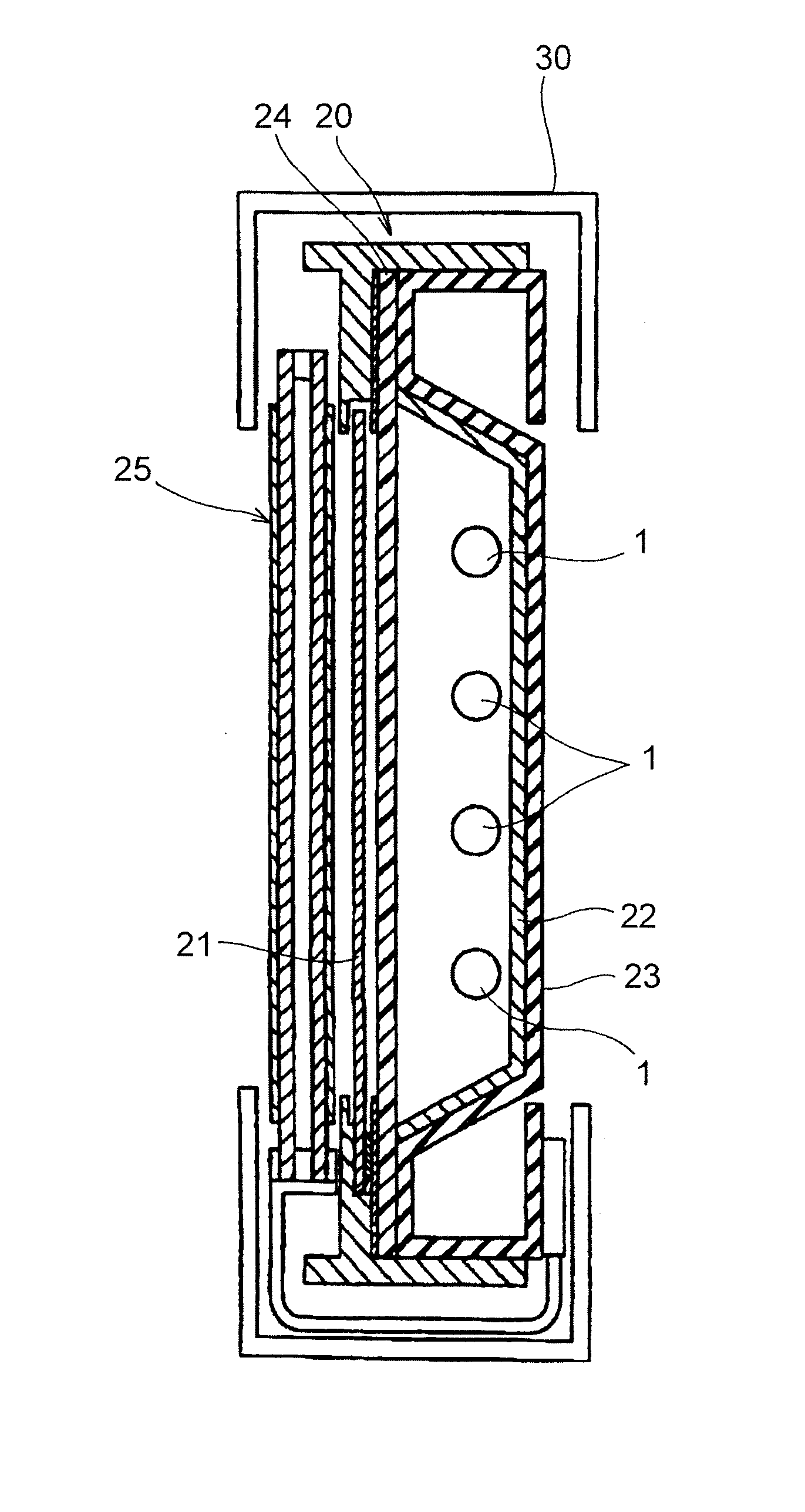
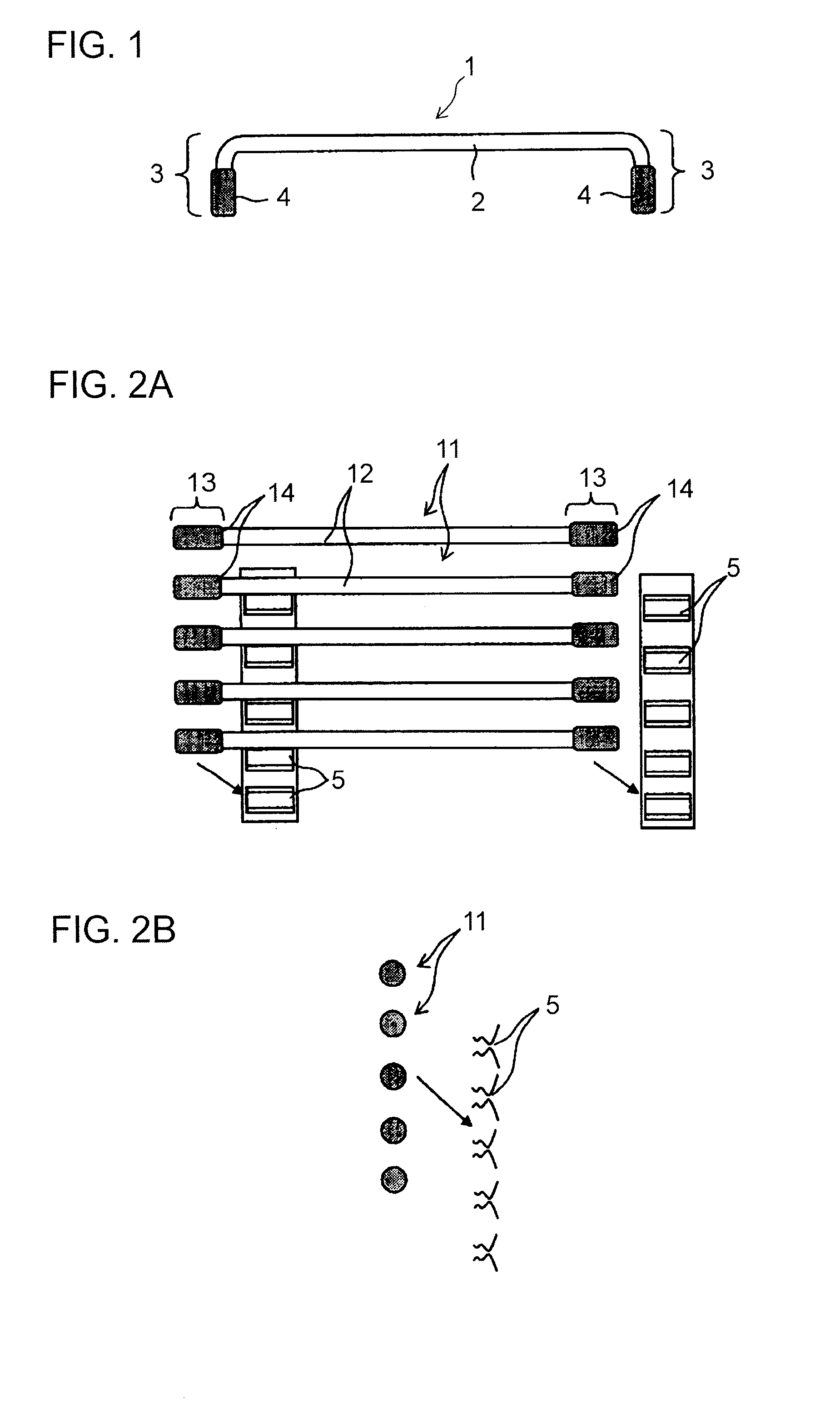
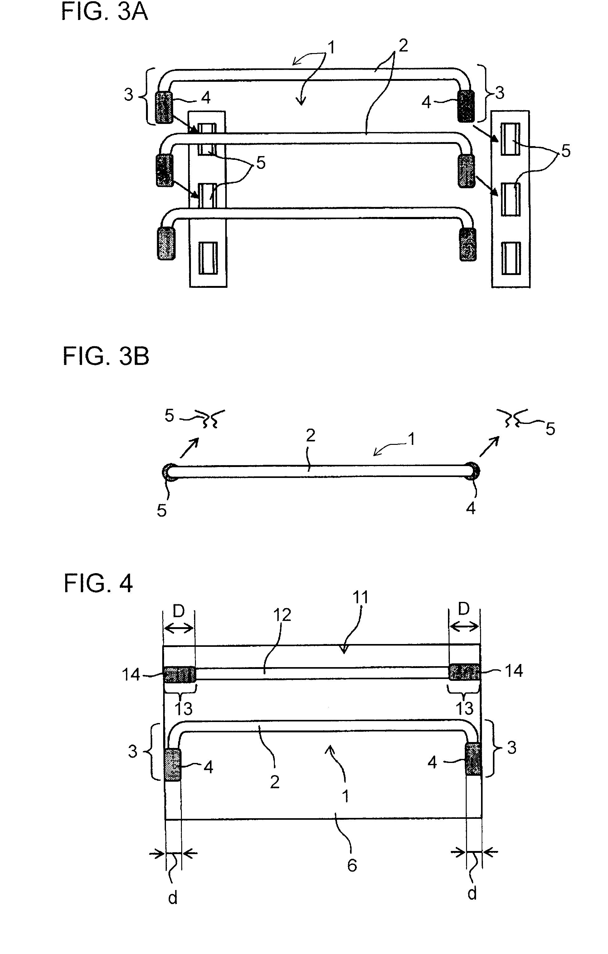
[0037] Hereinafter, referring to the drawings, preferred embodiments of the present invention will be described. For an external electrode fluorescent lamp (hereinafter also simply referred to as a lamp), an internal structure (including a filling) and electric configuration thereof, basic structure of a backlight unit loaded with the lamp, and the like are not essential matters of the present invention, and conventional examples and general matters of an external electrode fluorescent lamp is directly applicable to the external electrode fluorescent lamp of the present invention. Thus, these overlapping contents will be omitted from description and illustration. FIG. 1 shows the lamp, as a separate unit, of a first preferred embodiment of the present invention.

[0038] As shown in FIG. 1, the lamp 1 of this preferred embodiment preferably includes: a light-emitting section 2 with a linear tube axis; and external electrode sections 3 which are located at the both ends of the light-em...


PUM


Abstract

An external electrode fluorescent lamp has external electrodes at opposite ends. The portions provided with the external electrodes are bent so that their axes are orthogonal to the axis of a light emitting sections. A conventional external electrode fluorescent lamp is not bent in its portions provided with external electrodes. Since the external electrodes of the external electrodes fluorescent lamps serve concurrently as holding sections for the fluorescent lamps the axial length is made greater than the outer diameter so as to provide sufficient strength. The width of the frame section of the fluorescent lamp of the invention when mounted on a backlight unit is smaller than the width of the frame section of conventional fluorescent lamp. Therefore, the effective light emitting area of the backlight unit can be enlarged.

Description

BACKGROUND OF THE INVENTION [0001] 1. Field of the Invention [0002] The present invention relates to an external electrode fluorescent lamp. [0003] 2. Description of the Related Art [0004] An external electrode fluorescent lamp includes a linear glass tube having mercury or a rare gas filled therein with outer peripheral surfaces at the both ends thereof fitted with proximity conductors, silver paste, or the like as external electrodes. The external electrode fluorescent lamp, due to its structure of the electrodes provided outside, is said to be easy to process and capable of having a longer life. An example of such an external electrode fluorescent lamp is disclosed in Patent Document 1, JP-A-2003-168395 (see, in particular, FIGS. 2A, 2B, 3A, and 3B), described below. The invention described in Patent Document 1 relates to a structure for fitting the external electrode portion to a backlight unit. [0005] In this invention, aluminum foil is first attached as an external electrode t...

Claims


Application Information

Patent Timeline
Patent Type & Authority Applications(United States)
IPC IPC(8): H01J61/16H01J65/04
CPCG02F1/133604H01J65/046H01J65/00
Inventor TAKATA, YOSHIKI
Owner SHARP KK
Why Eureka
Try Eureka