Method and apparatus for operating a steam cycle process with a lubricated expander

a technology of lubricating expanders and steam cycle processes, which is applied in mechanical equipment, steam engine plants, machines/engines, etc., can solve the problems of premature aging, chemical conversion, and contamination of the components and working media with decomposition products of lubricant, and achieve the effect of effective separation of lubricating oil and economic operation of the cycle process over a long period of tim

Active Publication Date: 2016-07-05
SIEMENS AG +1
View PDF25 Cites 4 Cited by
  • Summary
  • Abstract
  • Description
  • Claims
  • Application Information

AI Technical Summary

Benefits of technology

[0013]It is an object of embodiments of the invention to provide a method for operating a steam cycle process in which the lubricant can be separated from the working medium in a highly effective manner downstream of the expander.
[0021]In the implementation of the method according to embodiments of the invention, the ionic liquid lubricant has good lubrication properties (viscosity, temperature stability, long-term stability, etc.), low corrosivity and low adverse environmental effects (disposal, toxicity, etc.).
[0039]It has been found that for a primary separation of the ionic lubricant from the working medium, near quantitative immiscibility of the working medium in the ionic lubricant is advantageous. The solubility of the ionic lubricant in the working medium may be <0.1 m %, <100 ppm, <10 ppm, or <1 ppm.
[0041]The ionic liquid lubricant may have no emulsifying effect, that is to say to have no or only minor properties which lower the interfacial surface tension.
[0064]Here, the lubricant reservoir may very generally be formed by at least one separation device in which the ionic liquid is separated from the working medium in a single-stage or multi-stage process. The separation device thus performs a dual function, acting firstly as a reservoir for the ionic liquid or also as a reservoir for the working medium and secondly, in its original function, as a separator, which saves components and thus also saves installation space. In this connection, it is particularly advantageous for the lubricant reservoir to be formed by the at least one separation device as described above which is arranged downstream of the expander and to which is supplied the mixture of working medium and ionic liquid passing from the expander.
[0066]Since it is the case not only that the lubricant circuit is contaminated with blow-by vapors but also that the working medium circuit is contaminated with ionic liquid, for example by a lubricant film which forms on the wall in the working chamber of a piston of a piston expander, it is provided in a further embodiment that the vaporous working medium which is discharged from the vessel and which is possibly contaminated with ionic liquid is supplied to the at least one separation device arranged downstream of the expander, to which separation device is also supplied the working medium passing from the expander and contaminated with ionic liquid. In this case, the vaporous working medium may be discharged from the vessel to be supplied, before being supplied to the at least one separation device, to a condenser in which the vaporous working medium is liquefied. The vessel may also be connected to the separation device in such a way that ionic liquid can flow from the separation device to the vessel and if appropriate in the opposite direction. With such an implementation according to the embodiment explained in more detail above, it is ensured in a simple manner that the ionic liquid does not accumulate to excessively large quantities in the working medium or in the working medium circuit. This increases operational reliability and also permits an optimized, small design and dimensioning of the apparatus and pipelines for the steam cycle process.

Problems solved by technology
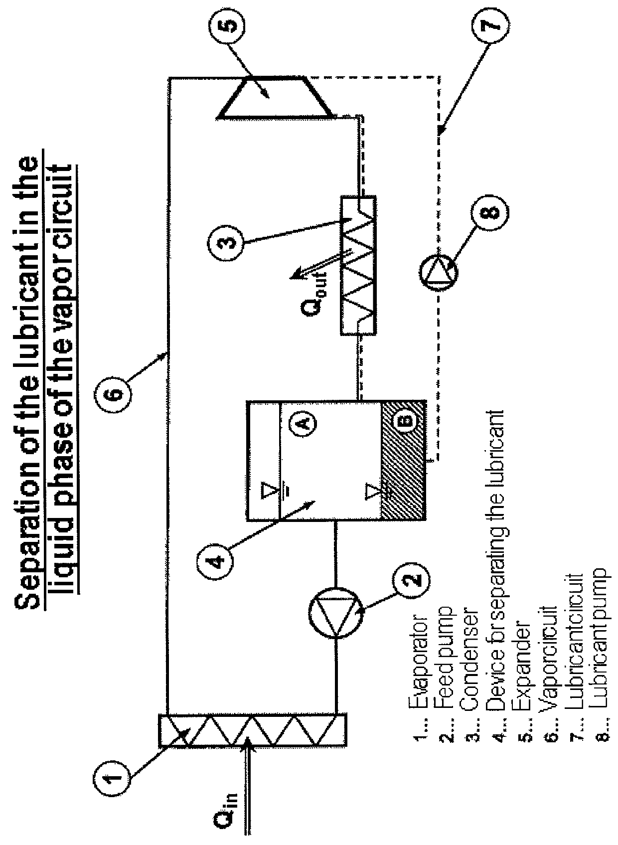
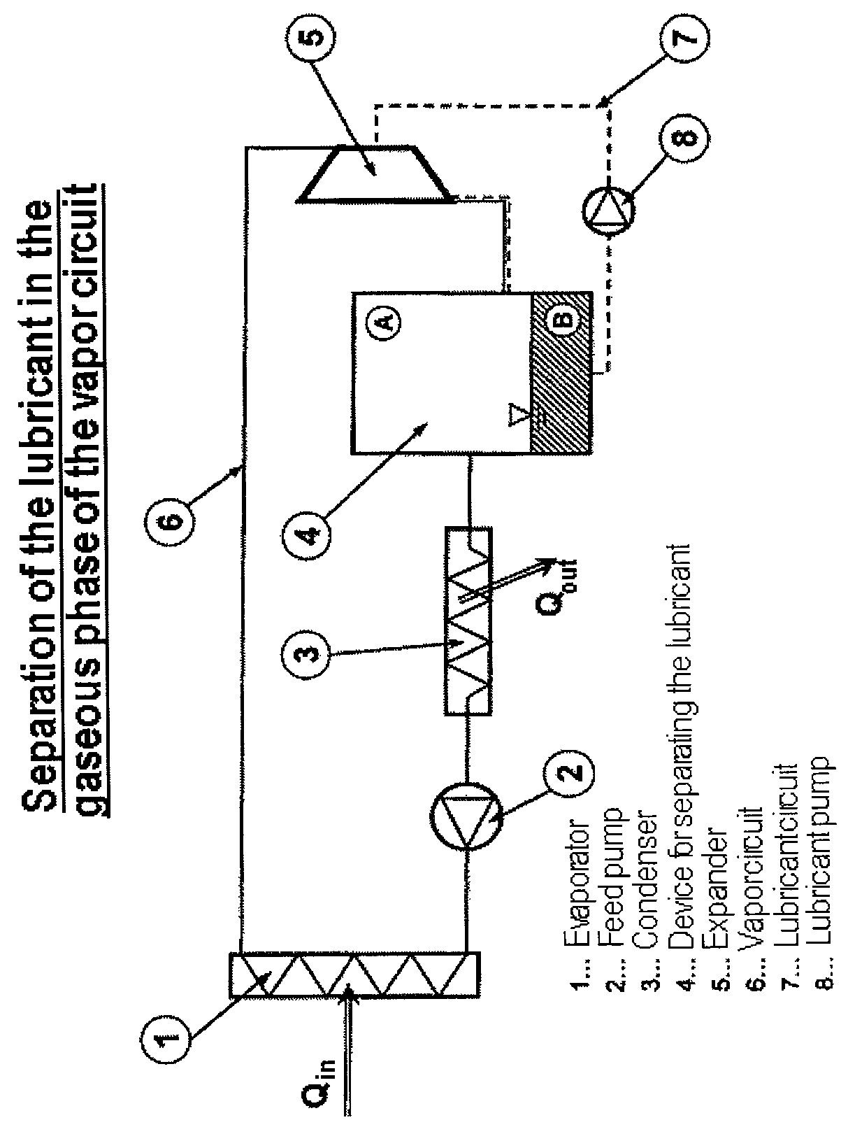
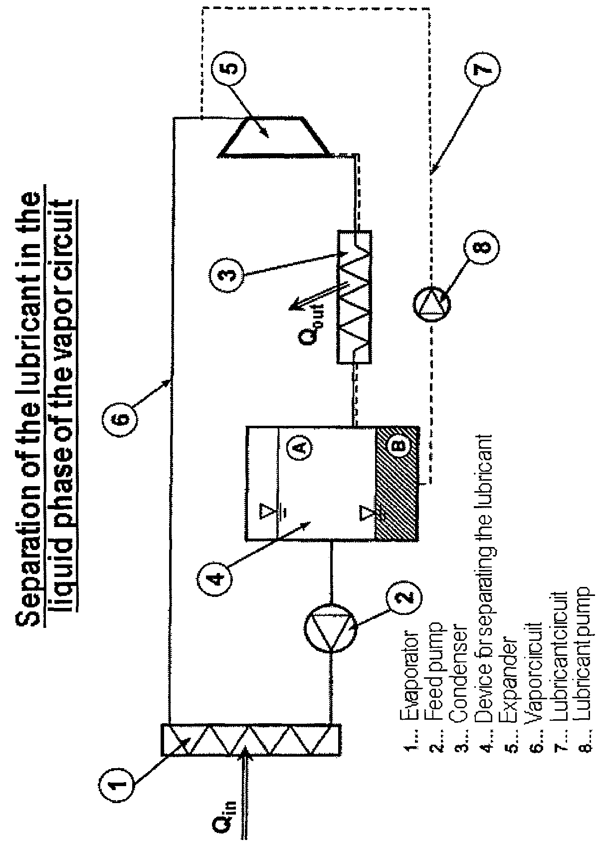
The effective separation of the oil and vapor circuits reliably prevents the lubricating oil from passing into the hot evaporator region and, there, leading to contamination of the components and of the working media with decomposition products of the lubricant.
As a result, some of the lubricant passes into the evaporator by means of the transport of the heat carrier medium in the cycle process, and in the evaporator the lubricant is exposed to high temperatures which lead to premature aging, chemical conversion (for example cracking) and ultimately thermal breakdown of the lubricant.
The lubricant is thus changed in terms of its properties, and can thus no longer adequately perform its lubrication functions.

Method used


Image

  • Method and apparatus for operating a steam cycle process with a lubricated expander
  • Method and apparatus for operating a steam cycle process with a lubricated expander
  • Method and apparatus for operating a steam cycle process with a lubricated expander

Examples


experiment 1

[0090]Case A: Separation by Gravity

[0091]50 g of 1-ethyl-3-methylimidazolium ethyl sulfate (ionic liquid) were stirred vigorously with 50 g of 1,1,3,3-tetramethyl disiloxane (vapor-generating working medium) in a closed round-bottomed flask for 2 hours by means of a magnetic stirrer and in a heating bath at a temperature of 80° C., which is a typical application temperature. The mixture was transferred into a shaking funnel and shaken very vigorously by hand for one minute. After the end of the shaking process, it was observed that a clean phase separation took place within a few seconds. After a waiting time of 2 minutes, which is a typical standing time for a phase separation by gravity in the typical application, the two phases were separated and poured, for measurement, into sample bottles.

[0092]Case B: Separation by Filtration

[0093]The process described above with respect to Case A was repeated with a second sample, wherein in addition to the separation by gravity, the separate...

experiment 2

[0101]50 g of 1-ethyl-3-methylimidazolium ethyl sulfate (ionic liquid) were stirred vigorously with 50 g of hexamethyl disiloxane (vapor-generating working medium) in a closed round-bottomed flask for 2 hours by means of a magnetic stirrer and in a heat bath at a temperature of 80° C. (typical application temperature). The mixture was transferred into a shaking funnel and was shaken very vigorously by hand for 1 minute. After the end of the shaking process, it was observed that a clean phase separation took place within a few seconds. The rest of the experimental procedure took place as in Experiment 1, described above. The linear regression of the calibration curve R2 was better than 0.95.

Results:

Concentration of the 1-ethyl-3-methylimidazolium Ethyl Sulfate in Hexamethyl Disiloxane

[0102]Case A (separation by gravity): 350 ppm[0103]Case B (separation by centrifuging): 55 ppm[0104]Case C (separation by centrifuging and filtration): 26 ppm

Estimation of the Remaining Working Medium in...

experiment 3

[0106]50 g of 1-ethyl-3-methylimidazolium methane sulfonate (ionic liquid) were stirred vigorously with 50 g of 1,1,3,3-tetramethyl disiloxane (vapor-generating working medium) in a closed round-bottomed flask for 2 hours by means of a magnetic stirrer and in a heat bath at a temperature of 80° C. (typical application temperature). The mixture was transferred into a shaking funnel and was shaken very vigorously by hand for 1 minute. After the end of the shaking process, it was observed that a clean phase separation took place within a few seconds. The rest of the experimental procedure took place analogously to Case C in Experiment 1, described above. The linear regression of the calibration curve R2 was better than 0.95.

Results:

Concentration of the 1-ethyl-3-methylimidazolium Methane Sulfonate in 1,1,3,3-tetramethyl Disiloxane

[0107]Case C (separation by centrifuging and filtration): 23 ppm

Estimation of the Remaining Working Medium in the Ionic Liquid:

[0108]The working medium 1,1,3,...


PUM

PropertyMeasurementUnit
temperatureaaaaaaaaaa
melting pointsaaaaaaaaaa
densitiesaaaaaaaaaa

Abstract

Embodiments of the invention relate to a method for operating a steam cycle process performed in an apparatus having an evaporator or steam generator for the evaporation of a liquid working medium and an expander, which is lubricated by a lubricant, for the performance of mechanical work. The method comprises a) supplying the liquid working medium to the evaporator, in which it evaporates and is fed to the expander in the form of steam; b) supplying an ionic liquid, which at room temperature forms two liquid phases with the liquid working medium, to the expander as a lubricant; and c) separating the ionic liquid forming the lubricant for the expander from the working medium upstream of the evaporator.

Description

CROSS-REFERENCE TO RELATED APPLICATIONS[0001]This is a U.S. national stage of application No. PCT / EP2011 / 002573 filed 24 May 2011. Priority is claimed on German Application No. 10 2010 022 408.1 filed 1 Jun. 2010, the content of which is incorporated herein by reference in its entirety.BACKGROUND OF THE INVENTION[0002]1. Field of the Invention[0003]The invention relates to a method for operating a steam cycle process with a lubricated expander based on the positive displacement principle, and to an apparatus for operating a steam cycle process.[0004]2. Background of the Invention[0005]Steam cycle processes with expanders are known for example from DE 10 2007 020 086 D3. The expander may for example be in the form of a piston expander, vane expander, rotary piston expander, swashplate expander, oblique-disk expander, roots expander or screw expander. In the positive displacement principle, the fresh vapor conducted out of the vapor generator is conducted into the working chamber of t...

Claims


Application Information

Patent Timeline
Patent Type & Authority Patents(United States)
IPC IPC(8): F01K15/00C10M171/00F01K15/02F01K23/06F01K25/10
CPCF01K15/00C10M171/00F01K15/02F01K23/065F01K25/10C10M2215/224C10M2219/042C10M2219/044C10M2219/06C10M2223/04C10N2220/04C10N2220/302C10N2220/303C10N2220/305C10N2020/077C10N2020/103C10N2020/105C10N2020/101
Inventor ALMBAUER, RAIMUNDKALB, ROLANDKIRCHBERGER, ROLANDKLAMMER, JOSEF
Owner SIEMENS AG
Why Eureka
Try Eureka