X-ray ct apparatus and x-ray detecting apparatus thereof

Active Publication Date: 2010-09-16
TOSHIBA MEDICAL SYST CORP
View PDF28 Cites 6 Cited by
  • Summary
  • Abstract
  • Description
  • Claims
  • Application Information

AI Technical Summary

Benefits of technology

[0009]The present invention addresses the abovementioned problems and defects of the conventional X-ray CT apparatus and X-ray detecting apparatus and provides an improved high-resolution X-ray apparatus and a high-resolution X-ray detecting apparatus thereof that can eliminate the lack of projection data corresponding to

Problems solved by technology

It is impossible to construct such a circular arc-shaped detection unit in an integrated architecture.
As a result, X-ray penetrated through an object cannot be detected at positions corresponding to the gaps provided between each of two detection packs.
Thu

Method used


Image

  • X-ray ct apparatus and x-ray detecting apparatus thereof
  • X-ray ct apparatus and x-ray detecting apparatus thereof
  • X-ray ct apparatus and x-ray detecting apparatus thereof

Examples


Example

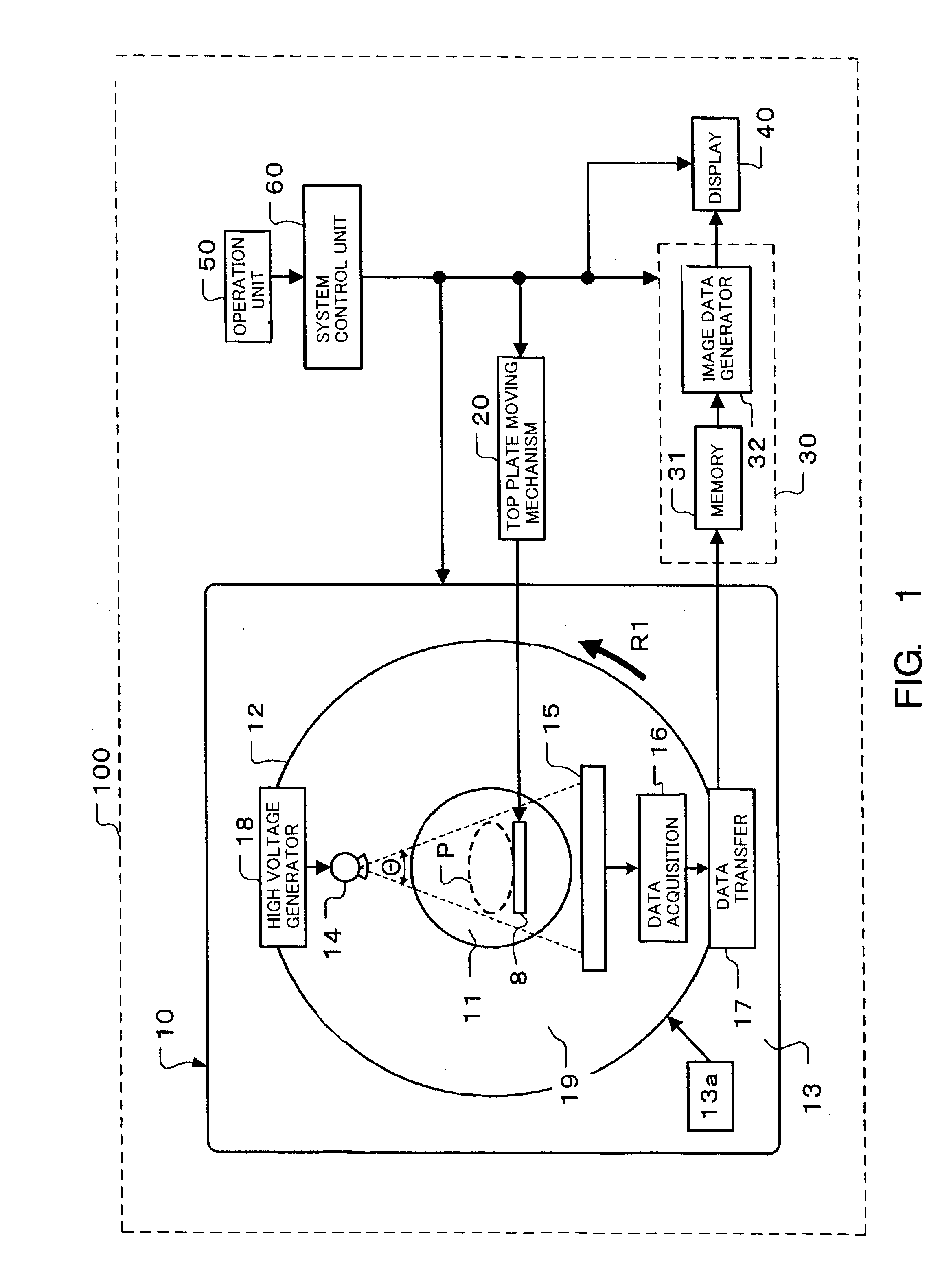
[0031]FIG. 1 illustrates a construction of an X-ray CT apparatus 100 consistent with the present invention. X-ray CT apparatus 100 includes a gantry 10 for performing X-ray imaging by irradiating X-ray onto an object P, a top plate moving mechanism 20, an image processing unit 30, a display unit 40, an operation unit 50 and a system control unit 60. Gantry 10 includes an almost cylindrical opening 11 for inserting an object P placed on top plate 8, a rotation unit 12 provided on a circumference of the opening 11 for rotating around a center axis of the opening 11 in a prescribed direction, and a gantry main body 13 for rotatably supporting the rotation unit 12. A rotation frame 19 in the rotation unit 12 is rotated in a prescribed direction, for instance, the R1 direction, by a rotation mechanism 13a provided in the gantry main body 13. The rotation frame is fixed to a main frame through main bearings.

[0032]Top plate moving mechanism 20 moves the top plate 8 in an elongate direction...


PUM


Abstract

A high-resolution X-ray apparatus and a high-resolution X-ray detecting apparatus includes a plurality of multi-slice X-ray detection packs held on the pair of guide rails by detachable tight fitting members. A detachable pressing board is provided on the pair of guide rails for fixing the plurality of detection packs so that edges of adjacent detection packs contact each other.

Description

CROSS-REFERENCE TO RELATED APPLICATIONS[0001]This application claims priority under 35 U.S.C. §119(a) from, and the benefit of, Japanese Patent Application No. 2009-53983 filed on Mar. 6, 2009, the contents of which are expressly incorporated herein by reference in their entirety.BACKGROUND OF THE INVENTION[0002]A. Field of the Invention[0003]The present invention relates to an X-ray computer tomography (CT) apparatus and an X-ray detection apparatus thereof, and more particularly, to a high-resolution X-ray apparatus and a high-resolution X-ray detecting apparatus including a plurality of X-ray detection packs that are detachably arranged in an X-ray scanning direction.[0004]B. Background of the Invention[0005]An X-ray CT apparatus reconstructs tomography images based on projection data acquired from various directions by scanning around an object. Usually, an X-ray tube and a detection unit are supported on a rotation frame in a gantry of an X-ray CT apparatus. The X-ray tube and ...

Claims


Application Information

Patent Timeline
IPC IPC(8): A61B6/03
CPCA61B6/035A61B6/4411A61B6/4085
Inventor YAOI, YOSHIAKI
Owner TOSHIBA MEDICAL SYST CORP
Why Eureka
Try Eureka