
Method for gas metal arc welding

Inactive Publication Date: 2015-03-12
LINDE AG
View PDF19 Cites 1 Cited by
  • Summary
  • Abstract
  • Description
  • Claims
  • Application Information

AI Technical Summary

Benefits of technology

The invention provides a method for controlling the detachment of wire electrode drops during cutting and welding processes. The addition of additional gas can affect the forces acting on the wire electrode drop, particularly via the placement of an arc. This allows for better control and management of the drop detachment process. The nozzle design allows for precise feeding of the additional gas to the wire electrode tip. Overall, this method improves the quality and accuracy of welding processes.

Problems solved by technology

However, arc operating conditions can only be used in limited current density or wire feed ranges in such GMA welding processes.
In order to reliably handle special welding tasks, e.g., those involving thin sheets and root passes, use must be made of arc types that generate a relatively cold molten bath (also referred to as cold processes) for this purpose; however, the latter are associated with a low melting deposition rate.
As a result, compromises have to be made with respect to the melting deposition rate.
GMA welding is associated with the generation of significant emissions.
On the other hand, GMA welding is associated with significant emissions in the form of dust, vapor and smoke, which can be absorbed through the respiratory system.
Therefore, GMA welding is linked with a strong influence on working safety and a high health risk.

Method used


Image

  • Method for gas metal arc welding
  • Method for gas metal arc welding

Examples


Embodiment Construction

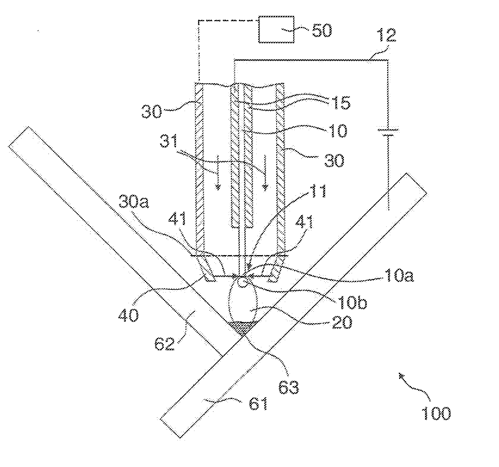
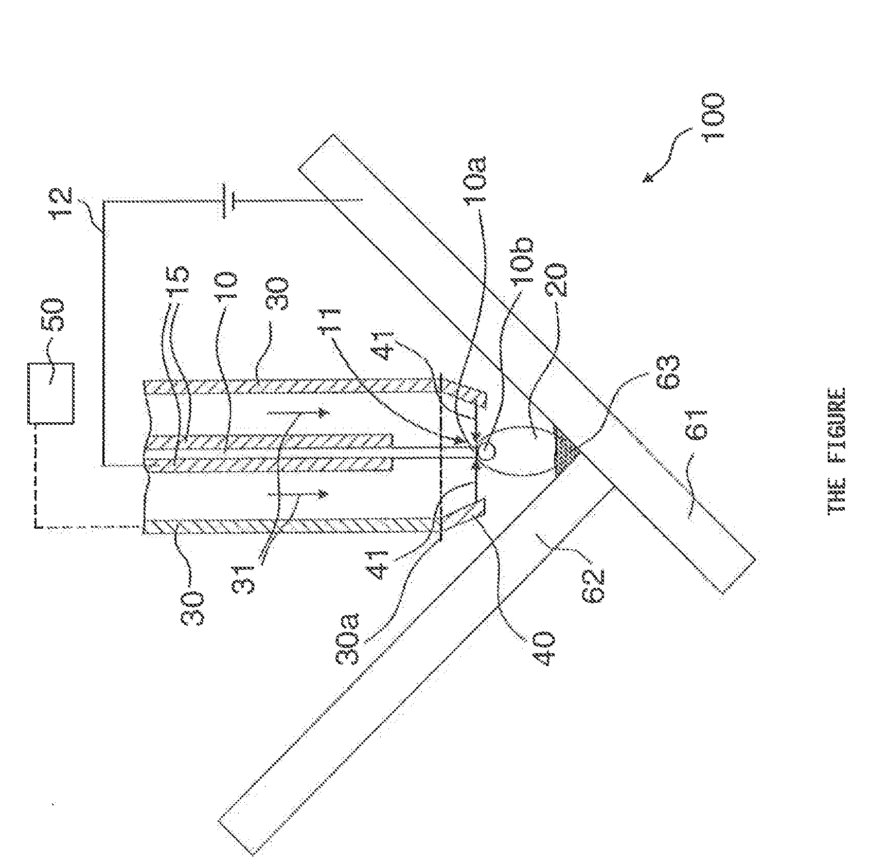
[0040]The gas metal arc welding device (GMA welding device) here schematically depicted on the FIGURE as a device for gas metal arc welding (GMA welding) is marked 100. The GMA welding device 100 is used in the joining process to weld a first work piece 61 with a second work piece 62.

[0041]The GMA welding device 100 exhibits a wire electrode 10 in the form of a wire, which is enveloped by a current contact sleeve 15. An electrical voltage is applied between the first work piece 61 and the current contact nozzle 15, denoted by reference number 12. An arc 20 is initiated via contact ignition and burns between the wire electrode 10 and first work piece 61. The high temperatures melt the tip 11 of the wire electrode 10. This results in a drop 10b of melted wire. The drop 11 finally detaches from the wire electrode 10, passes over to the molten bath 63, and forms the weld seam (joint connection between the work pieces 61 and 62). The wire 10 is here continuously fed. The formation of the...


PUM

PropertyMeasurementUnit
Fractionaaaaaaaaaa
Flow rateaaaaaaaaaa
Viscosityaaaaaaaaaa

Abstract

A method for gas metal arc welding, as well as to a device for gas metal arc welding and the use of an additional gas during gas metal arc welding, wherein a wire electrode is melted by an arc, wherein the arc burns between the wire electrode and a work piece, and an inert gas is supplied, and wherein an additional gas in the form of at least one additional gas flow directed toward the tip of the wire electrode is supplied in addition to the inert gas.

Description

CROSS REFERENCE TO RELATED APPLICATIONS[0001]This application claims priority from German Patent Application DE102013015171.6 filed Sep. 12, 2013.BACKGROUND OF THE INVENTION[0002]The invention relates to a method for gas metal arc welding, as well as to a device for gas metal arc welding and the use of an additional gas during gas metal arc welding, wherein a wire electrode is melted by an arc, wherein the arc burns between the wire electrode and a work piece, and an inert gas is supplied.[0003]Gas metal arc welding (GMA welding) involves an arc welding method that is used for the overlay welding, welding or soldering of one, two or more work pieces made out of metal materials. In an inert gas atmosphere, a wire electrode is here continuously fed in the form of a wire or belt and melted by an arc that burns between the work piece and wire electrode. The work piece here serves as a second electrode. In particular, the work piece here serves as a cathode, and the wire electrode as an ...

Claims


Application Information

Patent Timeline
IPC IPC(8): B23K9/16B23K9/173
CPCB23K9/173B23K9/164B23K9/295B23K9/324
Inventor SIEWERT, ERWANDRE EL, LAURENTIUS
Owner LINDE AG
Learn More