
Glycerin burning system

a burning system and glycerin technology, applied in the direction of combustion types, combustion using lumps and pulverulent fuels, lighting and heating apparatuses, etc., can solve the problems of large production and stockpiling of crude glycerin, add significant cost to the process, and existing burners cannot burn pure glycerin, so as to reduce the combustion speed

Inactive Publication Date: 2010-09-16
MASIN RADEK
View PDF31 Cites 3 Cited by
  • Summary
  • Abstract
  • Description
  • Claims
  • Application Information

AI Technical Summary

Benefits of technology

[0012]This mixture is propelled into a cylindrical combustion chamber where it ignites and burns in a swirling fashion. The far end of the combustion chamber is closed by a choke wall having a choke outlet. The choke outlet is an opening having an area which is smaller than the cross sectional area of the combustion chamber. The opening “chokes” the flow in order to reduce the combustion speed within the combustion chamber and thereby maintain the combustion speed below the flame propagation speed of the air / glycerin mixture.

Problems solved by technology

Although there are various uses for pure glycerin, the increase in demand for biodiesel has resulted in the production and stockpiling of large quantities of crude glycerin.
This adds significant cost to the process.
Existing burners cannot burn pure glycerin because the combustion air speed produced by conventional burners exceeds the flame propagation speed of the air-glycerin mixture.
This phenomenon is a major obstacle to the development of effective glycerin combustion systems.
However, the cost of the alcohol makes the entire process unprofitable.

Method used


Image

  • Glycerin burning system
  • Glycerin burning system
  • Glycerin burning system

Examples


Embodiment Construction

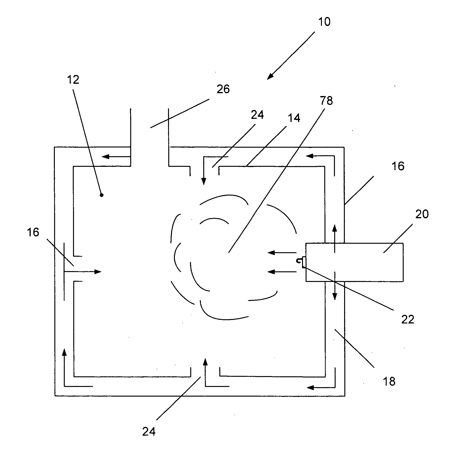
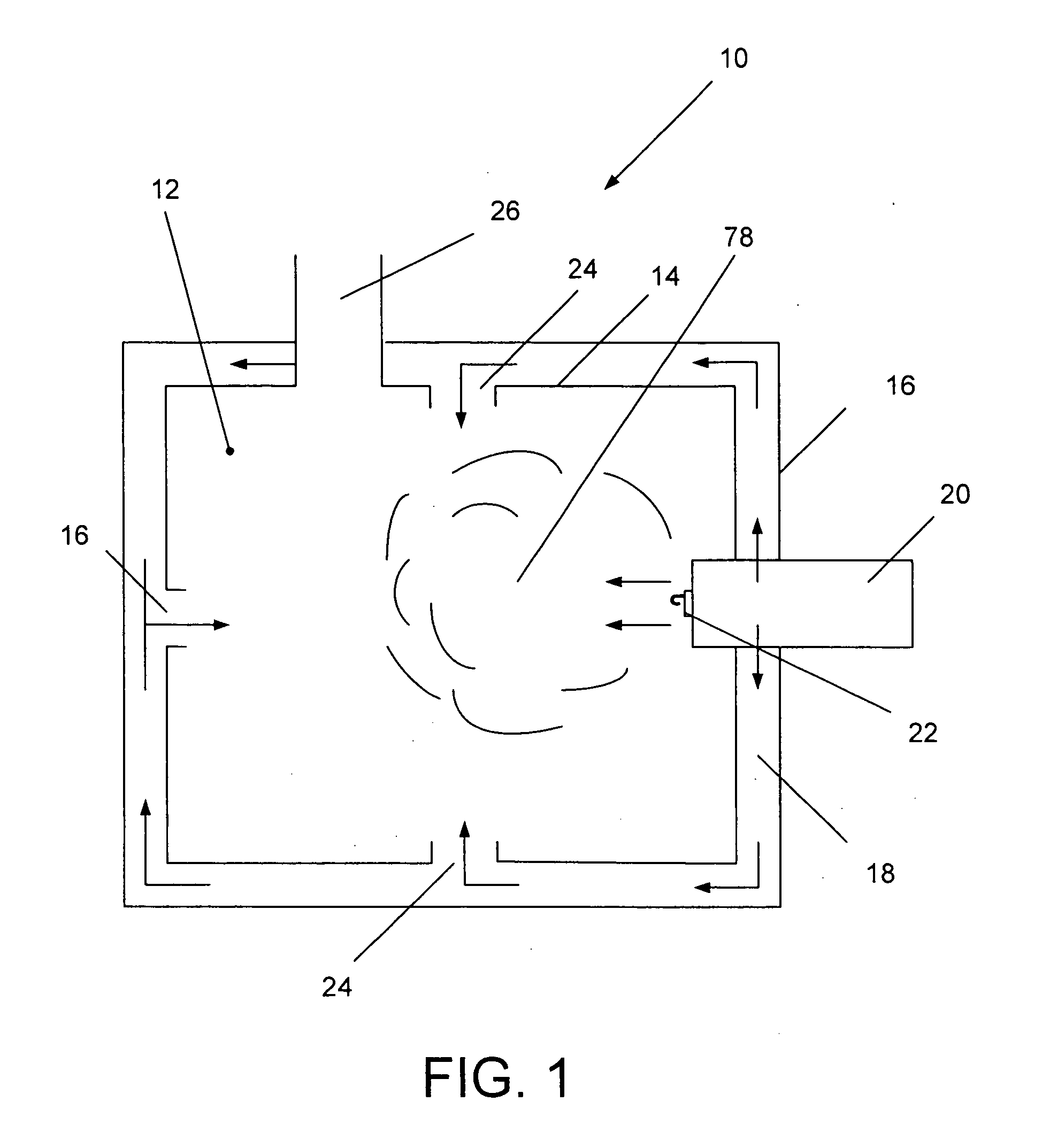
[0027]The present invention, glycerin burning system 10 is illustrated in FIG. 1. Glycerin burning system 10 may be used to burn a continuous feed of raw or pure glycerin. Glycerin burning system 10 generally includes burner 20 which expels glycerin through nozzle 22 into combustion chamber 12 where the glycerin is combusted in combustion zone 78. Exhaust gases are vented to the atmosphere through exhaust 26. Air is fed to burner 20 by a burner air blower and a portion of the air fed to burner 20 is diverted into conduit 18 which wraps around wall 14 of combustion chamber 12. Conduit 18 may be the interior region of a “jacket” surrounding wall 14 or any other conduit suitable for directing the flow of air around combustion chamber 12 while allowing the air to exchange heat with combustion chamber 12. Ports 24 and 16 are provided in wall 14 and direct heated air toward combustion zone 78. The direction of hot air towards combustion zone 78 serves two synergistic functions. First, the...


PUM


Abstract

A glycerin burning system having a specialized atomizing burner capable of combusting a continuous feed of crude or pure glycerin. The burner preferably includes an impingement nozzle. The nozzle has an internal distributor which mixes two fluid feed streams (glycerin and air) and expels the fluid through an orifice. The distributor has channels which cause the air to swirl before mixing with the glycerin. An impingement pin is provided outside the orifice. The rapidly ejected glycerin / air mixture strikes a target surface on the impingement pin which transforms the mixture into a fine mist having a reduced velocity. The nozzle is located on the central axis of a turbulator which surrounds the atomized spray with rapidly revolving air. An outlet choke is provided on the combustion chamber to limit the speed of the flow so that steady combustion is maintained.

Description

CROSS-REFERENCES TO RELATED APPLICATIONS[0001]This application is a continuation in part of U.S. application Ser. No. 12 / 069,076, which was filed on Feb. 7, 2008.STATEMENT REGARDING FEDERALLY SPONSORED RESEARCH OR DEVELOPMENT[0002]Not ApplicableMICROFICHE APPENDIX[0003]Not ApplicableBACKGROUND OF THE INVENTION[0004]1. Field of the Invention[0005]This invention relates to the field of waste product combustion. More specifically, the present invention comprises a glycerin burning system having a specialized atomizing nozzle for the combustion of glycerin.[0006]2. Description of the Related Art[0007]Glycerin, or glycerol, is a byproduct of biodiesel and soap manufacturing. Although there are various uses for pure glycerin, the increase in demand for biodiesel has resulted in the production and stockpiling of large quantities of crude glycerin. This trend is expected to continue.[0008]Currently there is a need for effective combustion systems for the disposal and heat recovery of glycer...

Claims


Application Information

Patent Timeline
IPC IPC(8): F23C5/00
CPCF23D7/00F23D11/103F23D11/24F23D11/386F23G2900/54402F23D2900/11001F23G5/446F23G7/04F23G2201/80F23D11/42
Inventor MASIN, RADEK
Owner MASIN RADEK
Learn More