Engine control device

a control device and engine technology, applied in the direction of electric control, ignition automatic control, machines/engines, etc., can solve the problems of low exhaust performance, inability to obtain high efficiency, and deterioration of combustion stability, so as to reduce the temperature of the air-fuel mixture, reduce the amount of fuel injection, and reduce the effect of the ratio of the amount of fuel

Active Publication Date: 2019-02-28
HITACHI ASTEMO LTD
View PDF0 Cites 4 Cited by
  • Summary
  • Abstract
  • Description
  • Claims
  • Application Information

AI Technical Summary

Benefits of technology

[0011]According to the present invention, as an engine temperature decreases, a ratio of a fuel injection amount during a compression stroke to a total fuel injection amount during one combustion cycle is increased. Thus, during lean combustion or EGR combustion, a decrease in a combustion speed due to a decrease in an engine temperature, that is, a decrease in a temperature of an air-fuel mixture in a combustion chamber can be suppressed by a high combustion speed of a rich-side air-fuel mixture accompanied by an increase in a ratio of a fuel injection amount during a compression stroke. Therefore, the deterioration of combustion stability of lean combustion or EGR combustion can be suppressed, and eventually a high efficiency performance and a low exhaust performance of the lean combustion or the EGR combustion can be maximized.
[0012]The problems, configurations, and effects other than those described above will become apparent from the description of the following embodiments.

Problems solved by technology

However, in the combustion that aims to achieve such high efficiency, the combustion stability is deteriorated according to an operating state or an environmental condition.
Therefore, a situation that cannot obtain high efficiency and low exhaust performance, at which the combustion can occur, may occur according to a condition.

Method used


Image

  • Engine control device
  • Engine control device
  • Engine control device

Examples


Embodiment Construction

[0023]Hereinafter, embodiments of the present invention will be described with reference to the drawings.

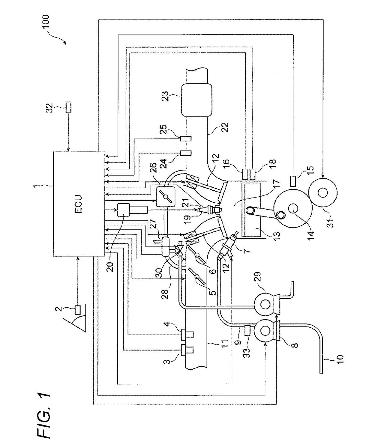
[0024]FIG. 1 is a system configuration diagram illustrating a schematic configuration of an automobile engine to which an engine control device (ECU) according to the present invention is applied.

[0025]An engine 100 according to an illustrated embodiment is an automobile engine which performs spark ignition stoichiometric air-fuel ratio combustion, spark ignition EGR combustion, and spark ignition lean combustion.

[0026]In the engine 100, an airflow sensor 3 which measures an amount of intake air to an intake pipe 11, a throttle 5 which adjusts a pressure in the intake pipe 11, an intake air temperature and humidity sensor 4 which is one embodiment of an intake air temperature and humidity detector and measures a temperature and a humidity of intake air, and a tumble valve 6 which makes the area of the intake pipe 11 variable are provided at each appropriate position of the intake...


PUM


Abstract

Provided is an engine control device capable of suppressing deterioration of combustion stability due to a change in engine temperature in an engine which performs lean combustion or EGR combustion. When lean combustion in which an air-fuel mixture leaner than a stoichiometric air-fuel ratio is burned or exhaust gas recirculation combustion in which a diluted air-fuel mixture is burned by re-suctioning exhaust gas discharged from the combustion chamber into the combustion chamber is performed, a ratio of a fuel injection amount during a compression stroke to a total fuel injection amount during one combustion cycle is increased as a temperature of an engine decreases.

Description

TECHNICAL FIELD[0001]The present invention relates to an engine control device mounted on a vehicle or the like.BACKGROUND ART[0002]From viewpoints of environmental preservation and energy conservation, an engine that is a power source mounted on a vehicle such as an automobile is required to have high efficiency and exhaust gas purification. For the high efficiency, it is effective to improve combustion performed in a combustion chamber inside the engine. As that means, there is lean combustion that burns air-fuel mixture leaner than a stoichiometric air-fuel ratio of fuel and air, exhaust gas recirculation (EGR) combustion (hereinafter referred to as EGR combustion) that re-suctions (also referred to as refluxes) exhaust gas discharged from a combustion chamber into the combustion chamber by burning air-fuel mixture in the combustion chamber and burns the air-fuel mixture diluted by the exhaust gas, or the like.[0003]However, in the combustion that aims to achieve such high effici...

Claims


Application Information

Patent Timeline
Patent Type & Authority Applications(United States)
IPC IPC(8): F02D41/40F02D41/04F02P3/045F02P9/00
CPCF02D41/402F02D41/04F02P3/045F02P9/002F02D2200/021F02D37/02F02D41/14F02D41/34F02D43/04F02P5/045F02P5/1502F02P5/1506Y02T10/40F02D41/02F02D43/00F02D45/00
Inventor OGATA, KENICHIROHARIHARA, YOSHINOBUOOBA, HISAHIROITAYA, TAKAKI
Owner HITACHI ASTEMO LTD
Why Eureka
Try Eureka