Tri-axis Angular Rate Sensor

a technology of angular rate sensor and tri-axis, applied in the direction of acceleration measurement using interia force, turn-sensitive devices, instruments, etc., to achieve the effect of improving angular ra

Active Publication Date: 2010-09-23
MEMSLINK TECH CO LTD
View PDF1 Cites 133 Cited by
  • Summary
  • Abstract
  • Description
  • Claims
  • Application Information

AI Technical Summary

Benefits of technology

[0005]It is in general an object of the invention to pro

Problems solved by technology

However, that solution requires three separate sensors and thre

Method used


Image

  • Tri-axis Angular Rate Sensor
  • Tri-axis Angular Rate Sensor
  • Tri-axis Angular Rate Sensor

Examples


Embodiment Construction

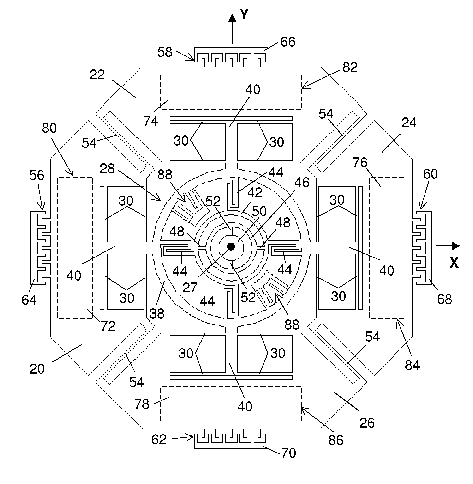
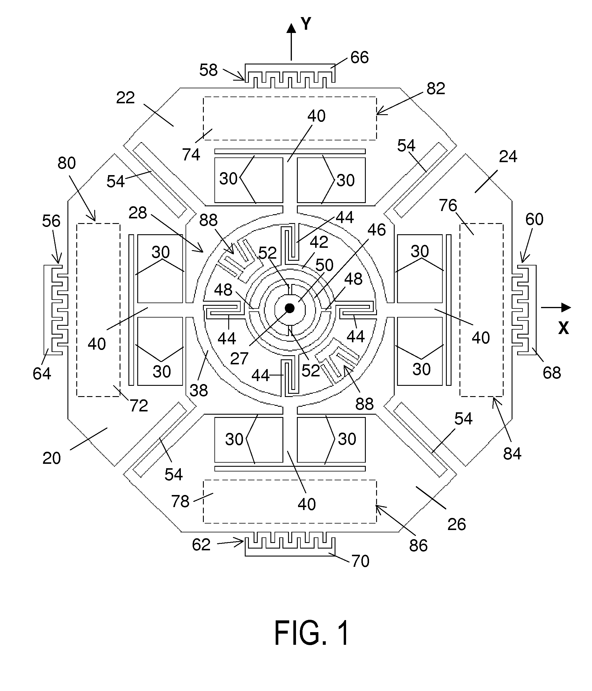
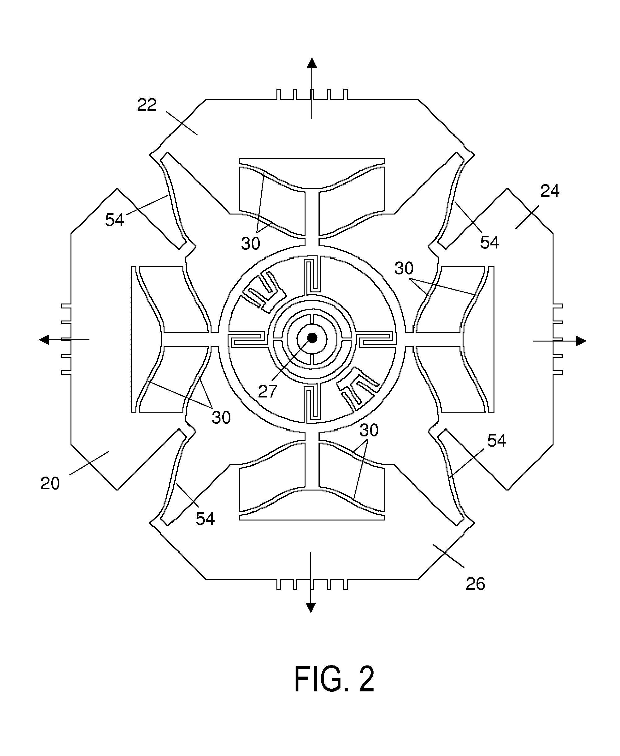
[0023]As illustrated in FIG. 1, the rate sensor has four generally planar butterfly-wing-shaped proof masses 20, 22, 24, 26 that lie in an x, y reference plane when the device is at rest. The proof masses are disposed around a center 27, which is the intersecting point of the x- and y-axes, with mass 20, 24 lying along the x-axis, and mass 22, 26 along the y-axis.

[0024]The proof masses are mounted on a supporting frame, or sense frame, 28 by flexible beams, or flexures, 30. These flexures constrain each one of the masses for linear movement in drive-mode relative to the sense frame along a predetermined axis, which is the drive axis of that mass. The drive axes of mass 20, 24 are in the x-axis, and the drive axes of mass 22, 26 are in the y-axis.

[0025]The flexures for each mass are relatively flexible in the direction along the drive axis of the mass, but relatively stiff in other directions. The use of multiple sets of flexures for each mass further suppresses possible relative mov...


PUM


Abstract

Angular rate sensor for detecting rotation about first, second and third mutually perpendicular input axes having a plurality of generally planar proof masses coupled together for linear drive-mode oscillation along multi-directional drive axes in a plane formed by the first and second input axes. The masses are mounted on a generally planar sense frame for linear movements relative to the sense frame in drive-mode and for rotation together with the sense frame in sense modes. The sense frame is mounted for rotation with the masses in sense modes about the first, second, and third input axes independent of each other, in response to Coriolis forces produced by rotation of the masses about the first, second, and third input axes respectively. And capacitance sensors responsive to the rotational movements of the masses and the sense frame in sense modes are employed for monitoring rate of rotation.

Description

BACKGROUND OF THE INVENTION[0001]1. Field of Invention[0002]This invention pertains generally to angular rate sensors or gyroscopes, and more particularly, to a rate sensor for monitoring rotation about three input axes.[0003]2. Related Art[0004]Many applications in automotive and consumer markets require measurements of angular rate about three mutually perpendicular axes. Currently, the most common solution is to use three separate rate sensors with each measuring rotation about one axis. However, that solution requires three separate sensors and three independent integrated circuits for drive control and sensing.OBJECTS AND SUMMARY OF THE INVENTION[0005]It is in general an object of the invention to provide a new and improved angular rate sensor or gyroscope.[0006]Another object of the invention is to provide a rate sensor or gyroscope of the above character, which overcomes the limitations, and disadvantages of rate sensors of the prior art.[0007]These and other objects are achi...

Claims


Application Information

Patent Timeline
IPC IPC(8): G01C19/56
CPCG01C19/5719
Inventor MAO, MINYAO
Owner MEMSLINK TECH CO LTD
Why Eureka
Try Eureka