Eureka AIR delivers breakthrough ideas for toughest innovation challenges, trusted by R&D personnel around the world.

Apparatus having a movable body

a technology of movable bodies and apparatuses, applied in the direction of acceleration measurement using interia forces, turn-sensitive devices, instruments, etc., can solve the problems of poor detection accuracy, inability to independently detect the respective displacement in the x-axis direction and the z-axis direction, and conventional technologies that do not address the rotation of the first mass, etc., to achieve excellent resistance to oscillatory disturbances and excellent resistance to shocks

Active Publication Date: 2010-09-23
TOYOTA CENT RES & DEV LAB INC
View PDF29 Cites 4 Cited by
  • Summary
  • Abstract
  • Description
  • Claims
  • Application Information

AI Technical Summary

Benefits of technology

[0007]The teachings disclosed herein were conceived in order to solve the above problem. The present teachings aim at preventing displacement along the x-axis from influencing the detection of the displacement along the z-axis, by providing, in addition to the 2-DOF movable body (e.g., the x-z movable body), a 1-DOF movable body that is moved together with the 2-DOF along the z-axis but is not moved in the x-axis direction. According to the teachings disclosed herein, rotation of the 1-DOF movable body may also be prevented, and greater detection precision may be achieved as a result.
[0009]In the above apparatus, the first spring portions are provided at least at four positions that are symmetrical with respect to the x, y-axes that run through the center of the first movable portion within the x-y plane. Consequently, the first spring portions provided at least at those four positions surrounding the first movable portions significantly suppress the rotation of the first movable portion, even when a force is exerted on the first movable portion which would cause the first movable portion to rotate about the center thereof within the x-y plane. The first spring portions are flexible in the z-axis direction but stiff in the x-axis and the y-axis directions. As a result, the first movable portion can be prevented from rotating about the z-axis even when it is supported only on one first spring portion. The rotation of the first movable portion can be suppressed very strongly when the first movable portion is supported at least at four positions that are symmetrical with respect to the x, y-axes that run through the center of the first movable portion by the first spring portions which are flexible in the z-axis direction but stiff in the x-axis direction.
[0011]The above characteristics of the teachings disclosed herein can be exploited in various applications such as sensors in which measurement of acceleration in a predetermined direction is free of interference from acceleration in another direction, or in actuators that allow realizing accurate translational displacements in a predetermined direction. As a result of analysis and experimentation, the inventors of the present application have found that the above characteristics afford excellent resistance towards oscillatory disturbances, as well as excellent resistance to shocks. The resistance to oscillatory disturbances is a useful property when the present apparatus is installed in movable bodies such as automobiles. The resistance to shocks is a useful property for accident sensing in movable bodies such as automobiles.

Problems solved by technology

It is therefore difficult to independently detect the respective displacement in the x-axis direction and the z-axis direction.
Conventional technologies do not address the rotation of the first mass.
This gives rise to a mismatch between the displacement of the first mass in the z-axis direction and the displacement of the second mass in the z-axis direction, which in turn translates into poorer detection precision.
The above problem is particularly serious in the manufacture of devices that use materials which requires high temperatures in forming a film, such as polysilicon and SiGe.
Thermal stress is substantial in such cases, and hence warpage is likely to occur.
Depending on the apparatus, warpage (which is an example of the permanent strain) during manufacture can give rise to problems such as variability in offset values, and / or detection value shifts on account of temperature changes.

Method used


Image

  • Apparatus having a movable body
  • Apparatus having a movable body
  • Apparatus having a movable body

Examples


first embodiment

[0049]A. Configuration of an Angular Rate Sensor According to a

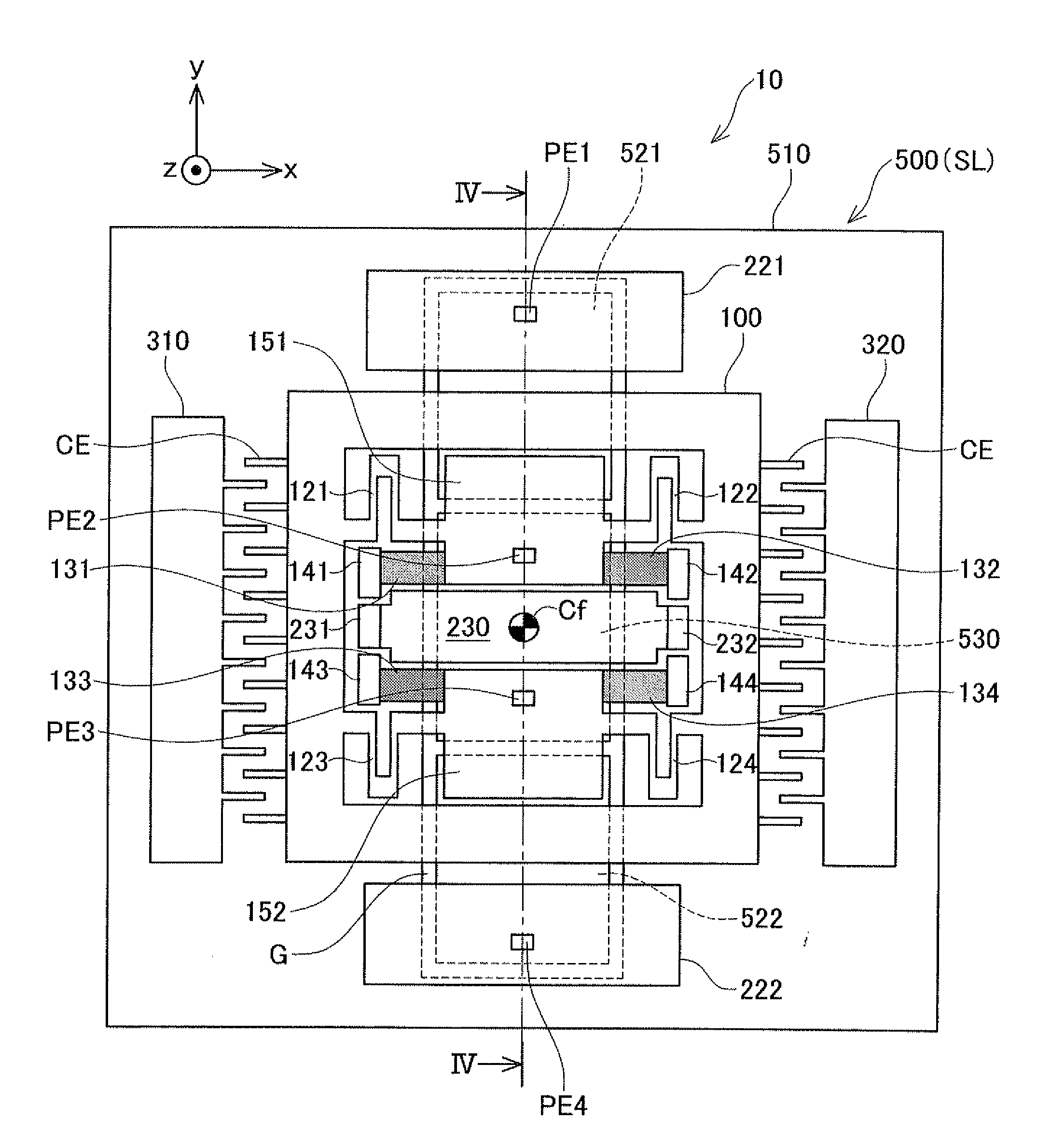
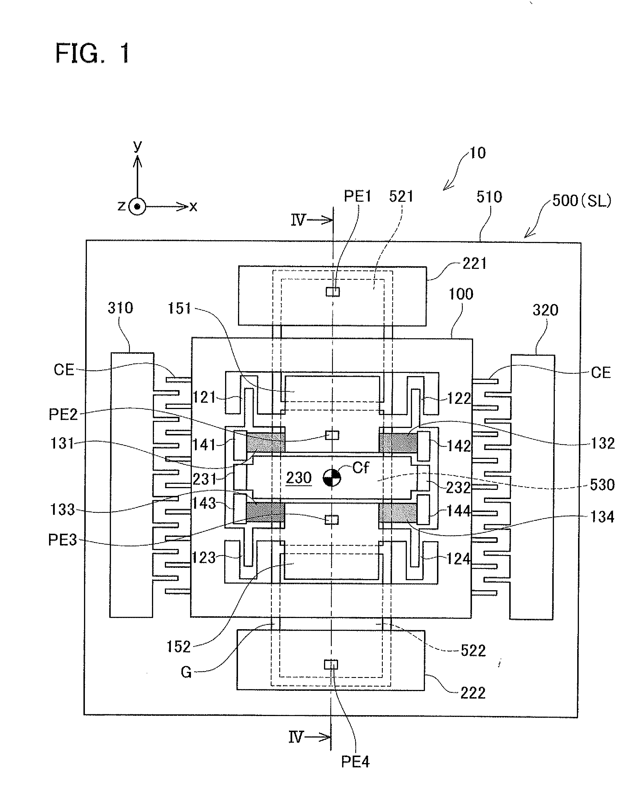
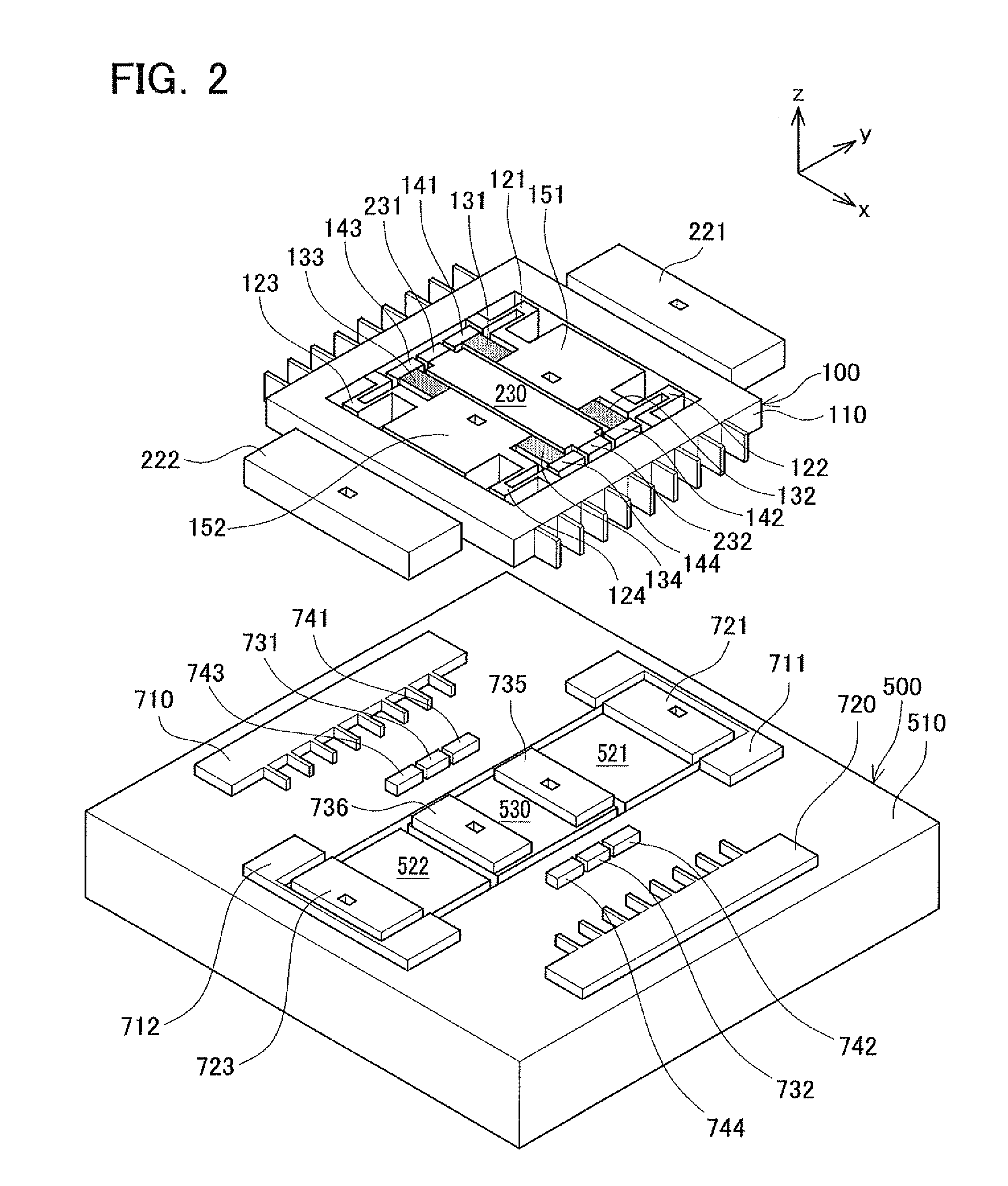
[0050]The configuration of the angular rate sensor according to the first embodiment will be described with reference to FIGS. 1-7. An angular rate sensor 10 comprises a movable body 100, three fixed electrodes 221, 222, 230, a pair of excitation electrodes 310, 320, and a support substrate 500 that supports the foregoing via a buried oxide film BL. The angular rate sensor 10 is composed with an SOI (Silicon on Insulator) substrate. The SOI substrate has a stacked structure comprising a conductive active layer WL (an example of the third layer) and the support substrate SL (an example of the first layer) with the buried oxide film BL (an example of the second layer) interposed therebetween. The movable body 100, the three fixed electrodes 221, 222, 230 and the pair of excitation electrodes 310, 320 are formed on the active layer WL, as illustrated in FIGS. 1 and 2. The active layer WL and the support substrate SL are ele...

second embodiment

[0073]B. Configuration of an Angular Rate Sensor According to the

[0074]FIG. 8 illustrates the configuration of an angular rate sensor 10a comprising a movable body 100a according to the second embodiment. FIG. 9 illustrates the configuration of the movable body 100a of the second embodiment. The movable body 100a of the second embodiment differs from the movable body 100 of the first embodiment in that, here, the joining portions 151, 152 of the first embodiment are changed to joining portions 151a, 152a of the second embodiment. Otherwise, the angular rate sensor 10a of the second embodiment shares the same features of the angular rate sensor 10 of the first embodiment.

[0075]The joining portions 151a, 152a of the second embodiment differ from the joining portions 151, 152 of the first embodiment (FIG. 4) in that the connection positions of the inner fixed portions 141 to 144 and the x-axis springs 121 to 124 are exchanged. Specifically, the positions of the inner fixed portion 141 ...

third embodiment

[0077]C. Configuration of an Angular Rate Sensor According to the Present Invention:

[0078]The third embodiment will be describes with reference to FIGS. 10-12. An angular rate sensor 10b of the third embodiment differs from the angular rate sensor 10 of the first embodiment in that the movable body 100 and the support substrate 500 of the first embodiment are changed to a movable body 100b and a support substrate 500b, and in that two penetrating electrodes PE2, PE3 of the first embodiment have been omitted.

[0079]The movable body 100b of the third embodiment differs from the movable body 100 of the first embodiment in that the movable body 100b is fixed to a support outer substrate 510b in a swastika layout. The specific dissimilar features are as follows (cf. FIG. 11).

(1) The pair of joining portions 151, 152 is changed to one joining portion 151b (an example of the first movable portion).

(2) The inner fixed portions 141 to 142 are changed to inner fixed portions 141b to 142b.

(3) ...


PUM


Abstract

An apparatus with a second movable portion that moves along an x-axis direction and a z-axis direction and a first movable portion that only moves along the z-axis direction is disclosed. The apparatus is provided with a fixed portion fixed to a support portion, a plurality of first spring portions connected to the fixed portion, a first movable portion connected to the plurality of first spring portions, a second spring portion connected to the first movable portion, and a second movable portion connected to the second spring portion. A spring constant of each of the plurality of first spring portions in the z-axis direction is lower than spring constants of each of the plurality of first spring portions in the x-axis and a y-axis directions respectively, and a spring constant of the second spring portion in the x-axis direction is lower than spring constants of the second spring portion in the y-axis and the z-axis directions respectively. The first movable portion is configured to move along the z-axis but not to move along the x-axis and the y-axis nor to rotate around the z-axis, and the second movable portion is configured to move along the x-axis and the z-axis with respect to the support portion.

Description

CROSS-REFERENCE TO RELATED APPLICATIONS[0001]This application claims priority under Paris convention based on (1) Japanese Patent Application No. 2009-066567 filed on Mar. 18, 2009 and (2) Japanese Patent Application No. 2010-43880 filed on Mar. 1, 2010, the contents of which are hereby incorporated by reference into this application.TECHNICAL FIELD[0002]The teachings disclosed herein relate to an apparatus having a movable body that can move in two directions. The present teachings may relate e.g., to an apparatus comprising a movable body that is moved along an x-axis when subjected to acceleration in an x-axis direction, and that is moved along a z-axis when subjected to acceleration in a z-axis direction. The present teachings may relate alternatively to an apparatus having a movable body that is moved along the z-axis when the movable body is subjected to angular rate about a y-axis while oscillating in the x-axis direction. The present teachings may relate to an apparatus comp...

Claims


Application Information

Patent Timeline
Patent Type & Authority Applications(United States)
IPC IPC(8): G01C19/56G01C19/5733G01C19/5762G01P15/125
CPCG01C19/5719G01P2015/082
Inventor AKASHI, TERUHISANONOMURA, YUTAKAFUJIYOSHI, MOTOHIROFUNABASHI, HIROFUMI
Owner TOYOTA CENT RES & DEV LAB INC
Why Eureka
Eureka Blog
Learn More