Headgear connection assembly for a respiratory mask

a headgear and connector technology, applied in the field of headgear connection assembly, can solve the problems of poor dexterity, patients may have difficulty in correctly joining the frame and headgear assembly with the connector, and certain connector arrangement is awkward or difficult to use, so as to achieve convenient and intuitive attachment and/or detachment, and easy accidental detachment. , the effect of quick attachmen

Inactive Publication Date: 2010-09-23
SOTEIRA
View PDF58 Cites 14 Cited by
  • Summary
  • Abstract
  • Description
  • Claims
  • Application Information

AI Technical Summary

Benefits of technology

[0009]One aspect of the present invention is to provide a respiratory mask assembly having a headgear connection assembly positioned between the frame and headgear assembly in a convenient and intuitive location for quick attachment and / or detachment by the patient, while not being easily detached accidentally.
[0011]Another aspect of the invention is to provide a headgear connection assembly which can be easily molded in a mask frame which includes a swivel elbow connector.

Problems solved by technology

Some patients have poor dexterity, and hence find certain arrangements of connectors awkward or difficult to use.
For example, some patients may have difficulty in correctly joining the frame and headgear assembly with the connector.
As a result, the connector may disengage during use or may become stuck so it becomes difficult for the patient to disconnect the frame from the headgear assembly.
Furthermore, some connectors are positioned on the frame of the mask assembly which makes it difficult for the user to see the connectors, because they are very close to the eyes or out of the range of vision of the patient.

Method used


Image

  • Headgear connection assembly for a respiratory mask
  • Headgear connection assembly for a respiratory mask
  • Headgear connection assembly for a respiratory mask

Examples


Embodiment Construction

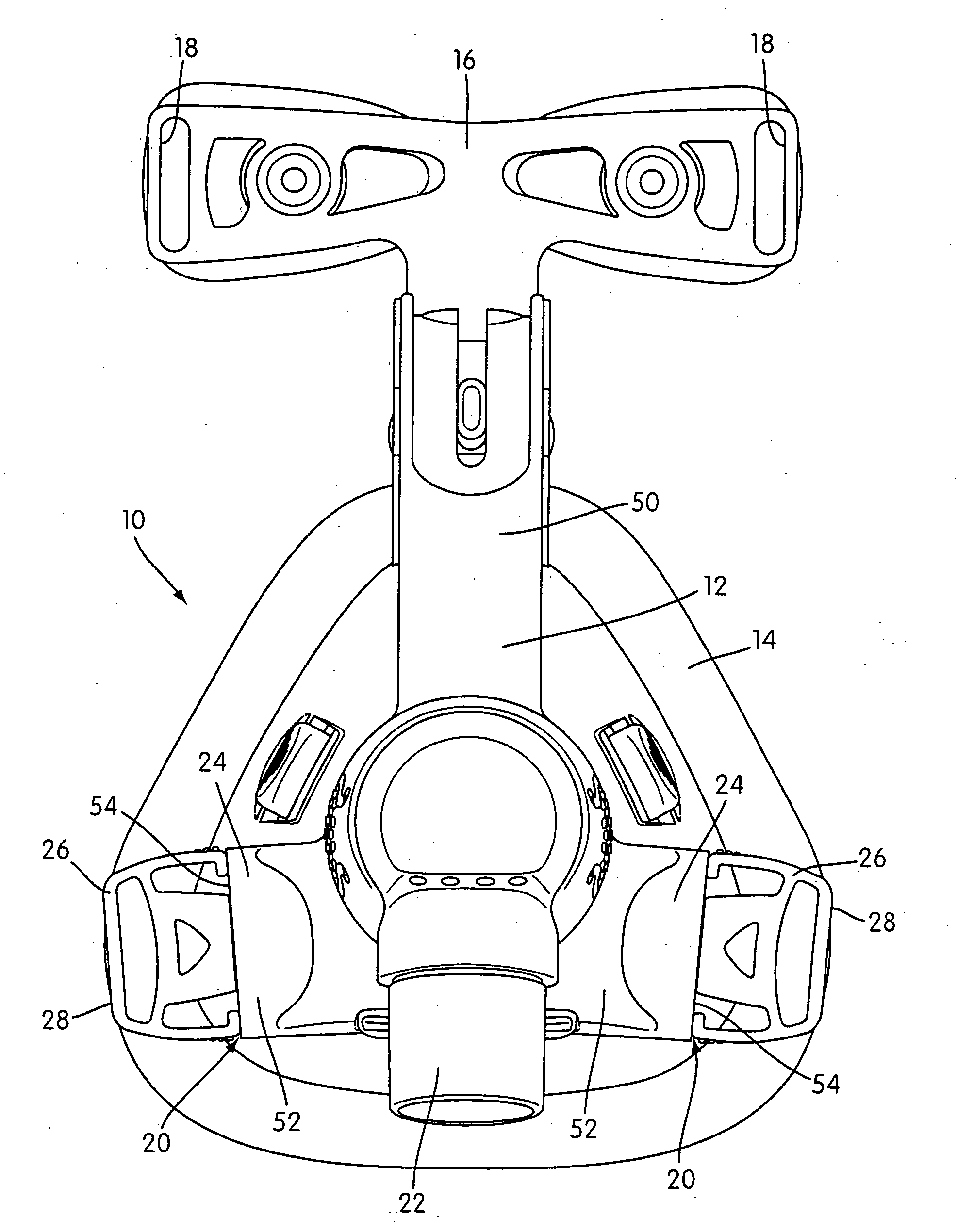
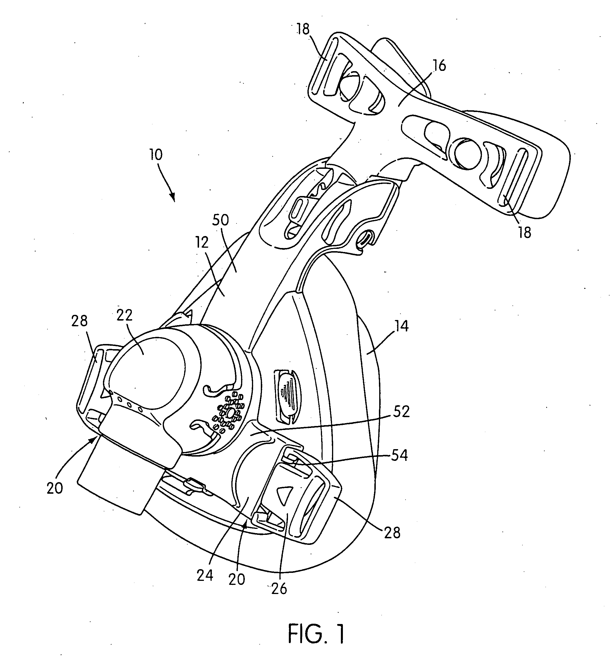
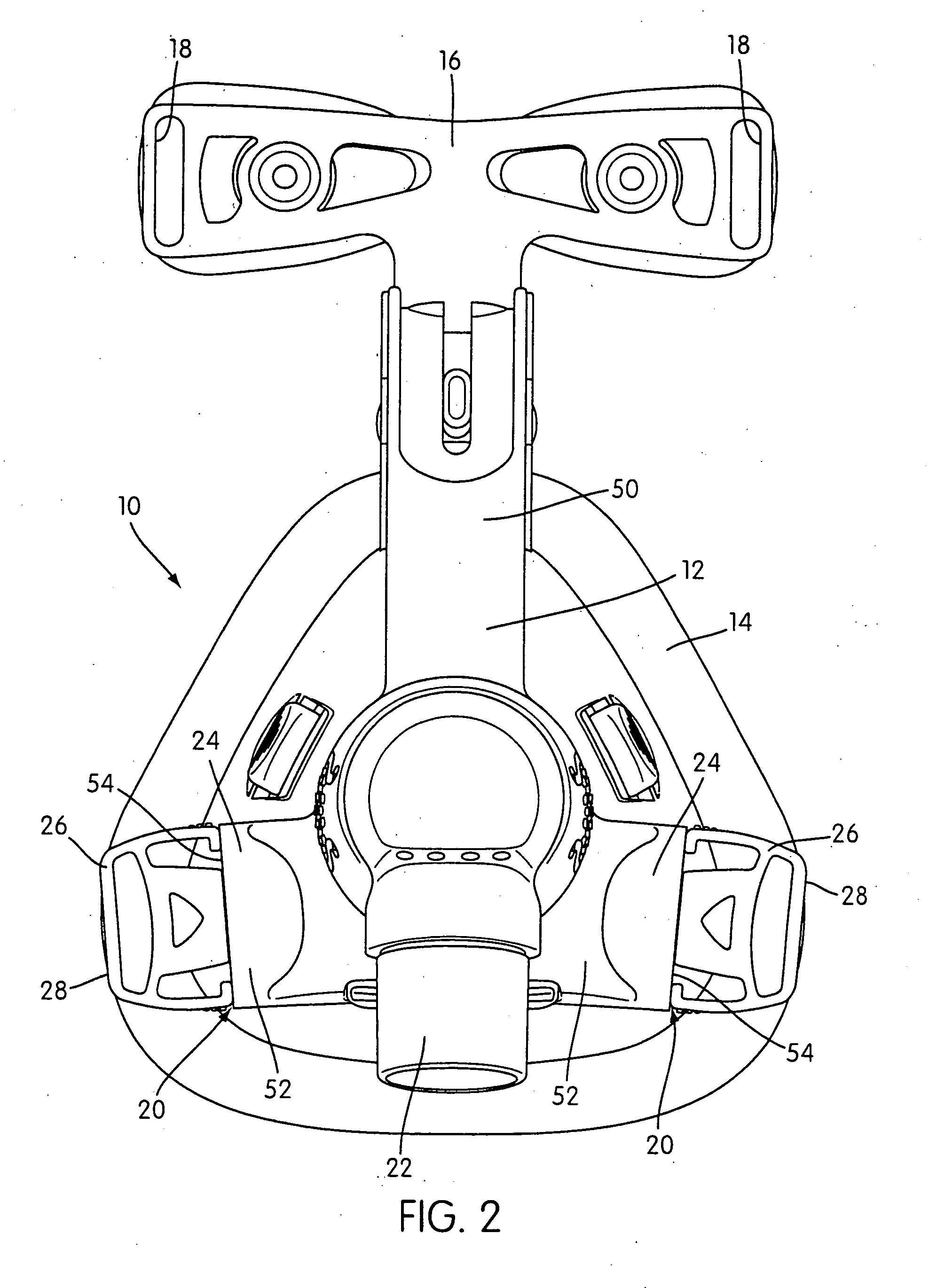
[0054]FIGS. 1 and 2 shown a respiratory mask assembly 10 that includes a frame 12 and a cushion 14 that may be permanently or removably connected to the frame 12. For example, the cushion 14 may be removably attached to the frame 12 with a cushion clip, straps, a friction or interference fit, and / or a tongue-in-groove arrangement, as is known in the art. However, the cushion 14 may be permanently attached to the frame 12 with glue and / or mechanical fastening means, for example.

[0055]A forehead support 16 is movably mounted to an upper portion of the frame 12. A headgear assembly (not shown) can be removably attached to the frame 12 to maintain the frame 12 and cushion 14 in a desired adjusted position on the patient's face. For example, the headgear assembly may include a pair of upper and lower straps with the upper straps removably connected to clip structures 18 provided on the forehead support 16 and the lower straps removably connected the frame 12 by a headgear connection asse...


PUM


Abstract

A respiratory mask assembly for delivering breathable gas to a patient includes a frame and at least one locking clip. The frame has a main body and a side frame member provided on each lateral side of the main body, at least one of the side frame members including a locking clip receiver assembly. The at least one locking clip has a main body providing a front portion adapted to be removably coupled with the at least one locking clip receiver assembly and a rear portion adapted to be removably coupled to a headgear assembly. The rear portion includes a cross bar that forms an opening through which a strap of the headgear assembly can pass and be removably coupled with the cross bar, and the front portion includes at least one resiliently flexible spring arm that is flexible within the plane of the main body.

Description

CROSS-REFERENCE TO PRIORITY APPLICATIONS[0001]The present application claims the benefit of U.S. Provisional Application Ser. No. 60 / 424,698 filed Nov. 8, 2002 and U.S. Provisional Application Ser. No. 60 / 467,571 filed May 5, 2003; and the present application is a Continuation-In-Part of U.S. Non-Provisional application Ser. No. 10 / 235,846 filed Sep. 6, 2002, which in turn claims priority to U.S. Provisional Application No. 60 / 317,486 filed Sep. 7, 2001 and U.S. Provisional Application Ser. No. 60 / 342,854 filed Dec. 28, 2001. Each of the above applications is hereby incorporated herein by reference in its entirety.FIELD OF THE INVENTION[0002]The present invention relates to a headgear connection assembly for use in removably attaching a headgear assembly to a frame of a respiratory mask assembly, the mask assembly being used for treatment, e.g., of Sleep Disordered Breathing (SDB) with Non-invasive Positive Pressure Ventilation (NPPV).BACKGROUND OF THE INVENTION[0003]Respiratory mas...

Claims


Application Information

Patent Timeline
Patent Type & Authority Applications(United States)
IPC IPC(8): A61M16/06A44B99/00A61M16/08
CPCA61M16/06A61M16/0683A61M16/08A61M2206/14A44B11/266A61M16/0825Y10T24/1391A61M16/0616A61M16/0633A61M16/0638A61M16/0057A61M16/0816A61M16/0611A61M16/065
Inventor LITHGOW, PERRY D.GUNEY, MEMDUHAMARASINGHE, AMAL S.FU, TIMOTHY TSUN-FAIROBINSON, GARY C.DAVIDSON, AARON SAMUELRAJE, MILIND CHANDRAKANT
Owner SOTEIRA
Why Eureka
Try Eureka