Oscillating Tool With Vibration Damping System

a technology of vibration damping and oscillating tools, which is applied in the direction of metal sawing apparatus, percussive tools portable, bulkheads/piles, etc., can solve the problems of slide guides being needed, affecting the ease of handling and may be disagreeable to users, and elements constituting such guides are subject to a certain degree of wear

Inactive Publication Date: 2010-09-23
C & E FEIN GMBH & CO KG
View PDF25 Cites 24 Cited by
  • Summary
  • Abstract
  • Description
  • Claims
  • Application Information

AI Technical Summary

Benefits of technology

[0010]It is a third object of the invention to disclose an oscillating tool which allows for continuous operation and has little wear.

Problems solved by technology

However, it has been found that vibrations may occur in such hand tools of that kind that use a vibration drive, which may impair the ease of handling and which may be disagreeable to a user.
Although the arrangement described at the outset has the effect to minimize oscillations, it has the disadvantage that slide guides are needed and that the elements constituting such guides are subject to a certain degree of wear, due to sliding friction.
This may be a disadvantage especially when the oscillating tool is driven at a high frequency and, in certain cases, with a large oscillation angle.

Method used


Image

  • Oscillating Tool With Vibration Damping System
  • Oscillating Tool With Vibration Damping System
  • Oscillating Tool With Vibration Damping System

Examples


Embodiment Construction

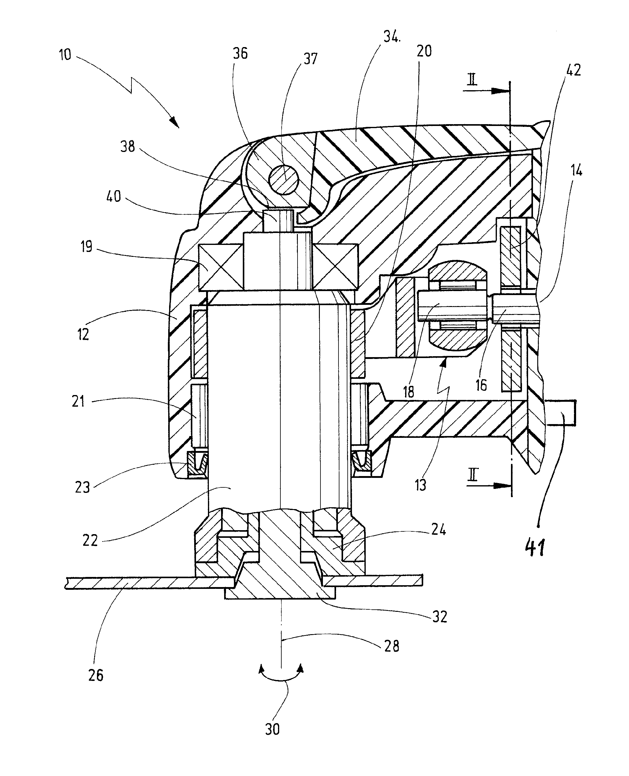
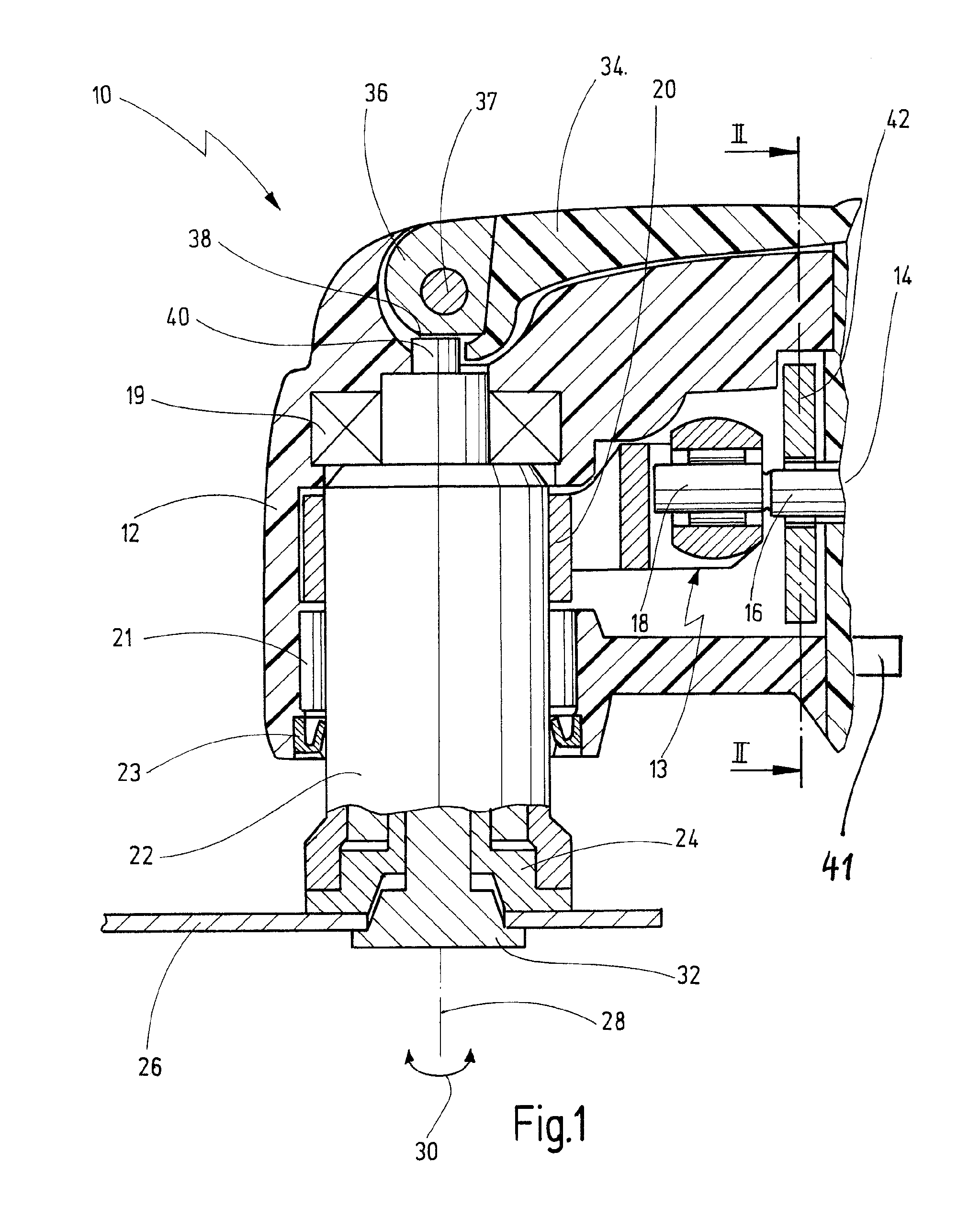
[0042]FIG. 1 shows a simplified view of an oscillating tool according to the invention, indicated generally by reference numeral 10.

[0043]The oscillating tool 10 comprises a housing 12, accommodating a motor 14 and an oscillation drive indicated generally by reference numeral 13, by which a drive shaft is driven about its longitudinal axis 28 in rotary and oscillating fashion, as indicated by double arrow 30. The shaft is driven at a high frequency of 5,000 to 25,000 oscillations per minute, for example, and with a small oscillating angle, typically in a range of between 0.5° and 7°.

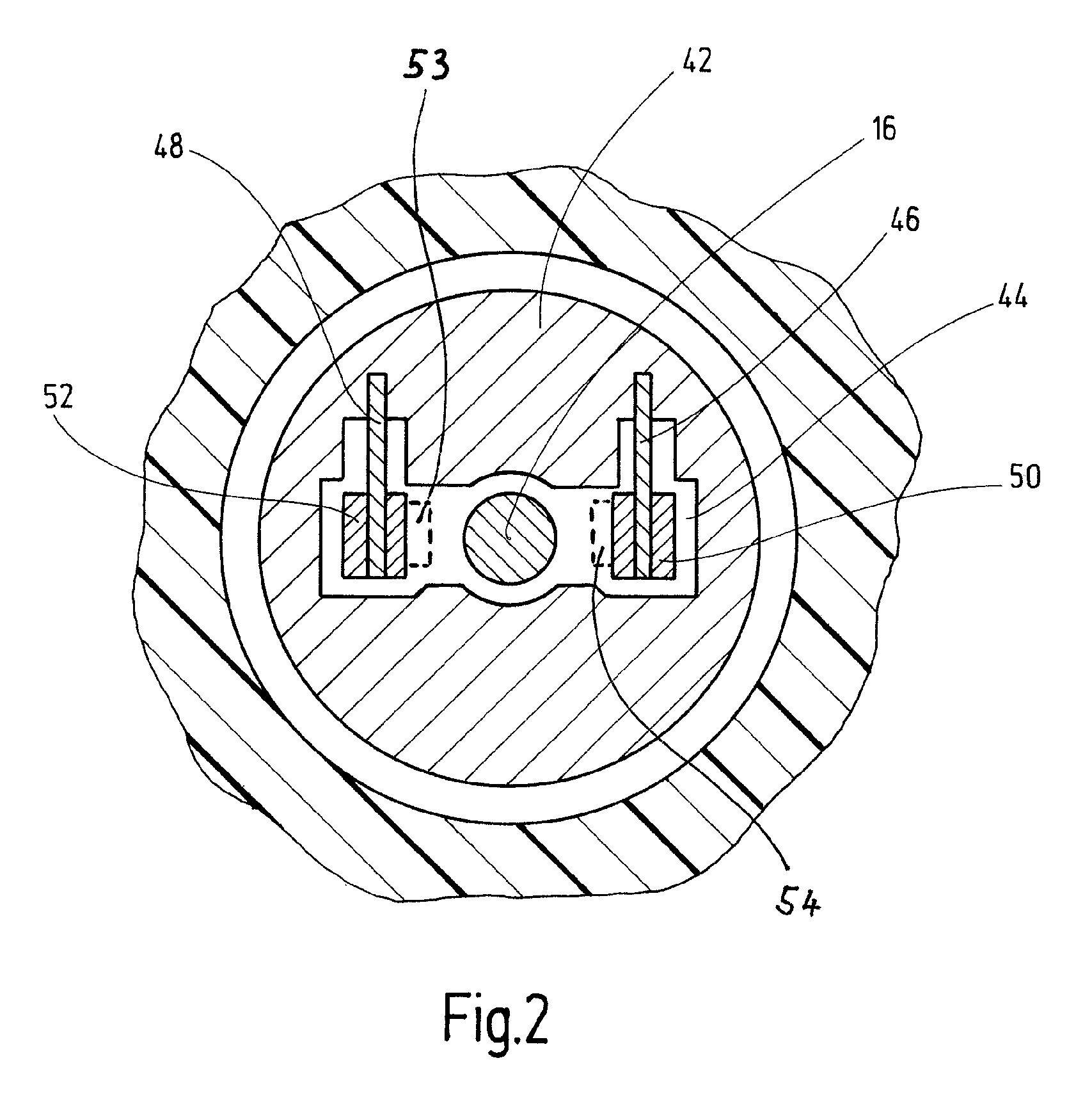
[0044]The oscillation drive 13 translates the rotary movement of the motor shaft 16 into an rotatingly oscillating movement of the drive shaft 22. The drive shaft 22, being oscillatingly driven by an eccentric portion 18 connected with the motor shaft 16, is positively connected with a rocker fork 20 for that purpose.

[0045]The drive shaft 22 is seated in the housing 12 via bearings 19, 21, and is scaled ...


PUM

PropertyMeasurementUnit
oscillation angleaaaaaaaaaa
harmonic frequenciesaaaaaaaaaa

Abstract

An oscillating tool comprises a housing that accommodates a motor which for driving a tool is coupled with a drive shaft via an oscillation drive, for driving it about its longitudinal axis rotatingly oscillatingly. For reducing vibrations, there is provided an inertial mass that is movably held on the housing via at least one spring element.

Description

BACKGROUND OF THE INVENTION[0001]The present invention relates to an oscillating tool with a housing that accommodates a motor which for driving a tool is coupled with a drive shaft via an oscillation drive for driving it rotatingly oscillating about its longitudinal axis.[0002]An oscillating tool of that kind is known from WO 2008 / 128804 A1.[0003]In the case of the known oscillating tool, the motor couples an oscillation drive in the form of an eccentric drive with a drive shaft for causing it to move about its longitudinal axis rotatingly oscillating.[0004]A mass-balancing arrangement intended to balance vibrations comprises an amplitude mass that is slidably arranged in a slide guide, and which is acted upon by the eccentric cam transmission. The amplitude mass performs an exclusively translational movement for which purpose the slide guide comprises a guide plate with a guide track, and a guide pin guided in the latter.[0005]Oscillating tools of that kind can be used in diverse ...

Claims


Application Information

Patent Timeline
Patent Type & Authority Applications(United States)
IPC IPC(8): B25F5/00
CPCB24B41/042B23D47/005B24B23/04B25F5/006B24B41/007B27B19/006
Inventor HEILIG, MARKBLICKLE, JUERGENSCHREIBER, ALFRED
Owner C & E FEIN GMBH & CO KG
Why Eureka
Try Eureka