
Wiring harness and method of forming a wiring harness

a wiring harness and wire harness technology, applied in the field of wiring harnesses, can solve the problems of high cost, bulky wiring harness, and hinder space saving, and achieve the effect of easy cutting by hand and good abrasion resistan

Inactive Publication Date: 2010-09-23
SUMITOMO WIRING SYST LTD
View PDF8 Cites 13 Cited by
  • Summary
  • Abstract
  • Description
  • Claims
  • Application Information

AI Technical Summary

Benefits of technology

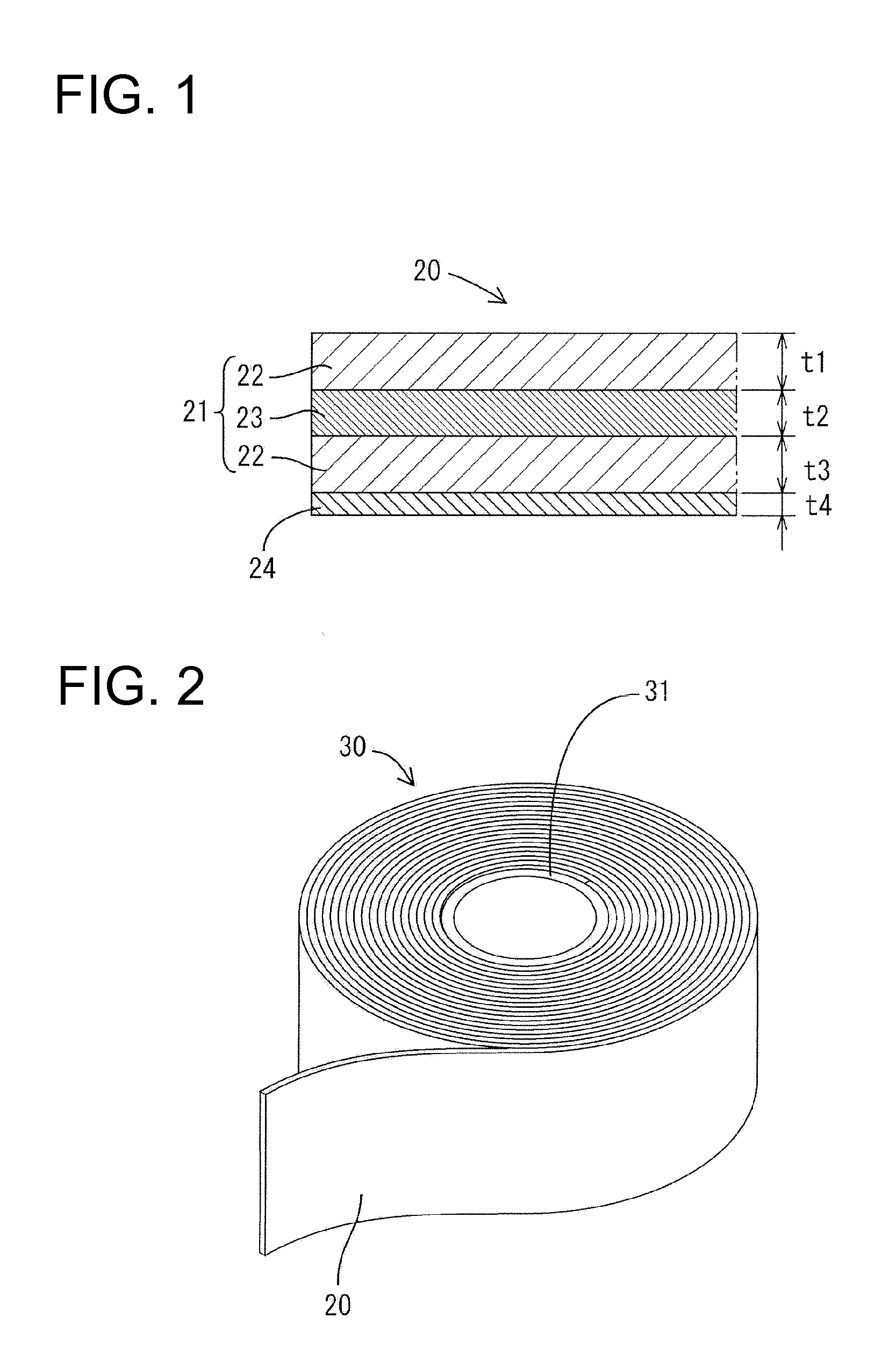
[0006]The invention is directed to a wiring harness with a protective tape wound around a cable bundle. The protective tape has a laminated base and an adhesive layer on the underside of the laminated base. The laminated base is formed by bonding two knitted and / or woven fabrics by a glue and / or adhesive. Thus, the base has a three-layer structure formed by the two fabrics that are bonded by the glue and / or adhesive. A load applied to the wiring harness is distributed mainly in the two fabrics to relax a stress. The protective tape has good abrasion resistance and can be cut easily by hand.
[0008]The wound tape increases the diameter of the wiring harness to a minimum level, which contributes to space and weight saving saving.

Problems solved by technology

High costs are associated with the method of Japanese Unexamined Patent Publication No. 2000-353432 due to the many parts and the many operation steps.
Hence, the wiring harness is bulky to hinder space saving.

Method used


Image

  • Wiring harness and method of forming a wiring harness
  • Wiring harness and method of forming a wiring harness
  • Wiring harness and method of forming a wiring harness

Examples


Embodiment Construction

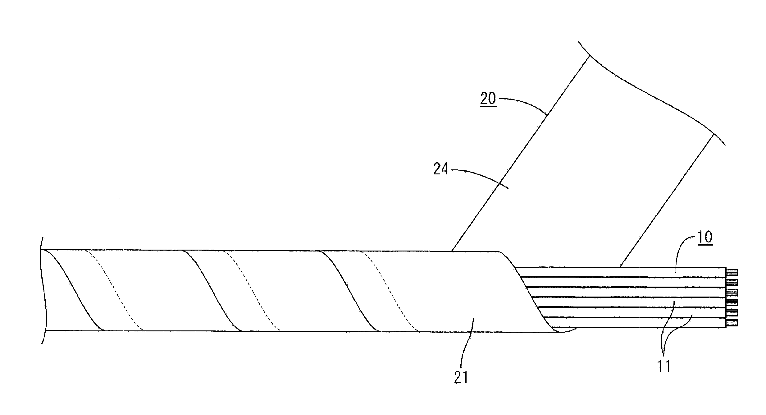
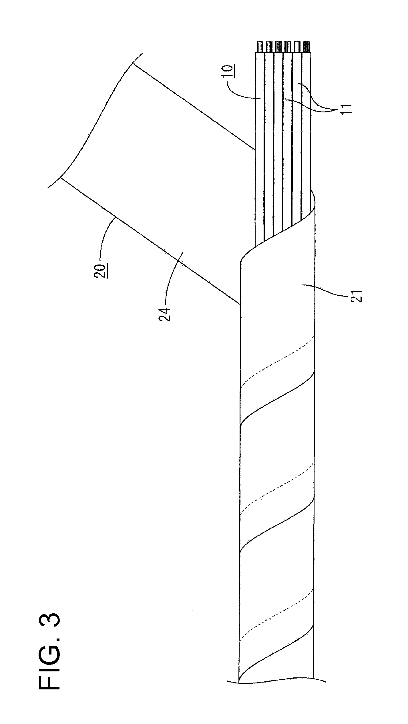
[0025]A first embodiment of the invention is described with reference to FIGS. 1 to 9. The first embodiment roughly has a protective tape 20 as a protective member wound around a cable bundle 10 of a wiring harness.

[0026]The cable bundle 10 has a plurality of insulated cables 11 and / or shielded cables bundle, as shown in FIG. 3.

[0027]As shown in FIG. 1, the protective tape 20 has a base material 21 and an adhesive layer 24 formed on the underside of the base material 21 to be held in contact with the outer circumferential surface of the cable bundle 10.

[0028]The base material 21 has a three-layer structure formed by bonding two knitted fabrics 22 by a glue or adhesive 23. Here, the “knitted fabric” is such that either warps or wefts are continuous strings of loops and the others are inserted through these loops. On the contrary, a “woven fabric” is a fabric formed by vertically or orthogonally intersecting warps and wefts.

[0029]The glue 23 preferably is a polyamide glue and preferab...


PUM

PropertyMeasurementUnit
total thicknessaaaaaaaaaa

Abstract

A protective tape (20) is composed of a three-layer base material (21) formed by bonding two knitted fabrics (22) by a glue (23) applied in dots, and an adhesive layer (24) formed on the underside of the base material (21). The base material (21) distributes an external load to the two knitted fabrics (22) for relaxing a stress. The protective tape (20) is difficult to abrade and also has a good hand cutting property. The protective tape (20) is wound spirally around the outer circumferential surface of a cable bundle (10) with lateral edges thereof overlapped while being dispensed from a roll (30), and the adhesive layer (24) on the underside is bonded to the outer circumferential surface of the cable bundle (10).

Description

BACKGROUND OF THE INVENTION[0001]1. Field of the Invention[0002]The invention relates to a wiring harness provided with a protective member and to a method of producing a wiring harness.[0003]2. Description of the Related Art[0004]Japanese Unexamined Patent Publication No. 2000-353432 discloses the use of a corrugated tube to protect a cable bundle of a wiring harness to be installed in an automotive vehicle or the like. More specifically, an inner tape is wound around a bundle of cables. The taped bundle of cables then is inserted through a longitudinal slit in a slit corrugated tube and an outer tape is wrapped around the corrugated tube to prevent the slit from being opened. High costs are associated with the method of Japanese Unexamined Patent Publication No. 2000-353432 due to the many parts and the many operation steps. Additionally, an accommodation rate of the cable bundle in the corrugated tube is suppressed, for example, to 80% to suppress opening of the corrugated tube w...

Claims


Application Information

Patent Timeline
Patent Type & Authority Applications(United States)
IPC IPC(8): H01B7/00H01B19/00C09J7/29
CPCC09J7/0296Y10T29/49227H02G3/0481C09J2400/263C09J7/29C09J2203/302
Inventor DOI, MASAYUKIMORII, TOSHITSUGUIMATOKU, ARISA
Owner SUMITOMO WIRING SYST LTD
Learn More