
Generation of a pulsed jet by jet vectoring through a nozzle with multiple outlets

a technology of pulsed jets and nozzles, applied in the field of jet propulsion and thrust vectoring, can solve the problems of large storage plenums, large flow fluctuations, and interruptions of discrete jet pulses exiting the nozzle, and achieve the effect of enhancing thrust and propulsive efficiency and being easy to implemen

Active Publication Date: 2010-09-23
SOUTHERN METHODIST UNIVERSITY
View PDF23 Cites 46 Cited by
  • Summary
  • Abstract
  • Description
  • Claims
  • Application Information

AI Technical Summary

Benefits of technology

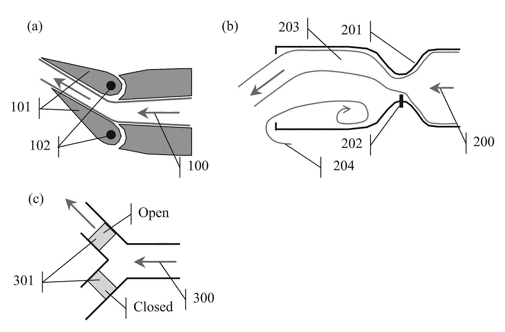
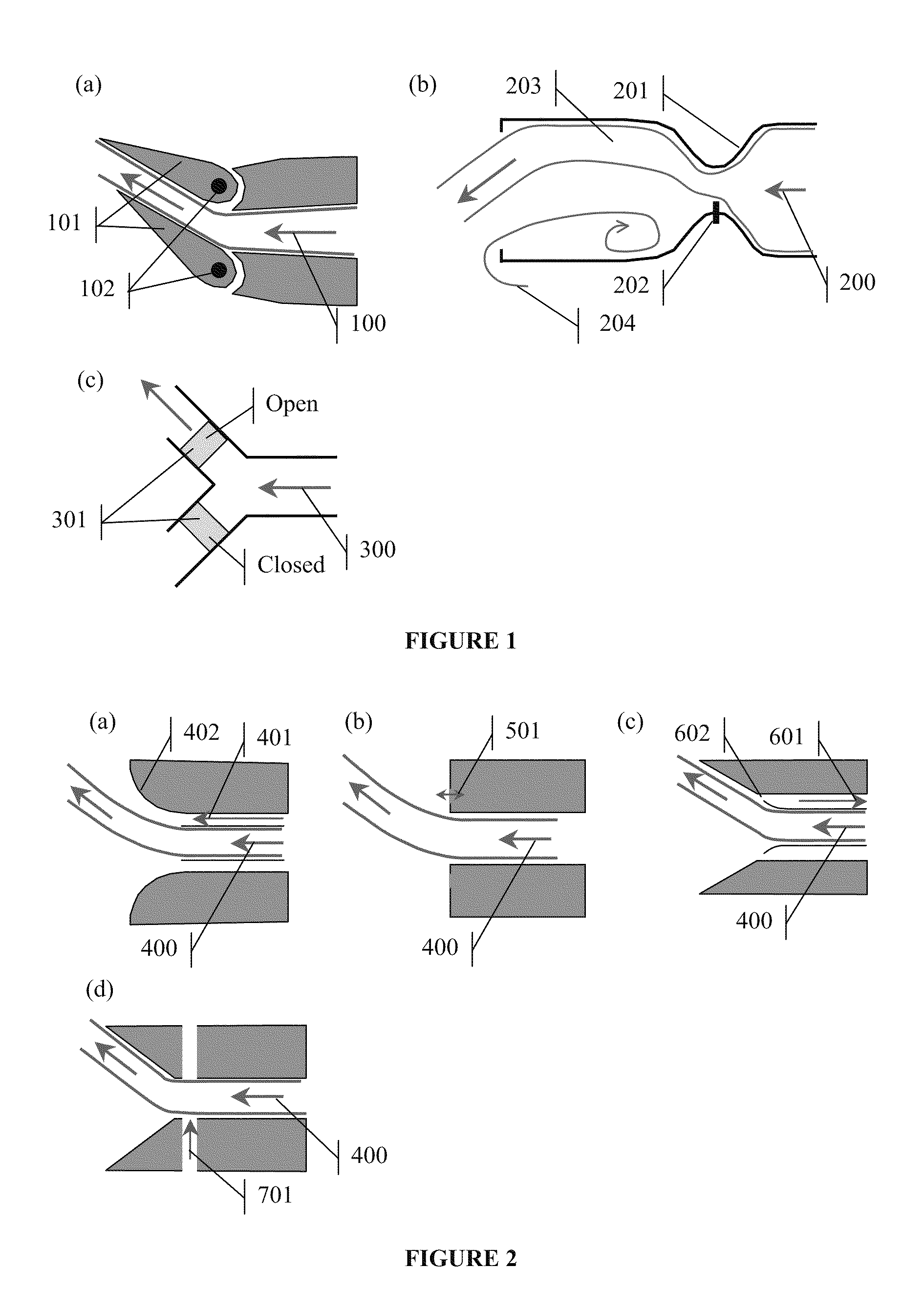
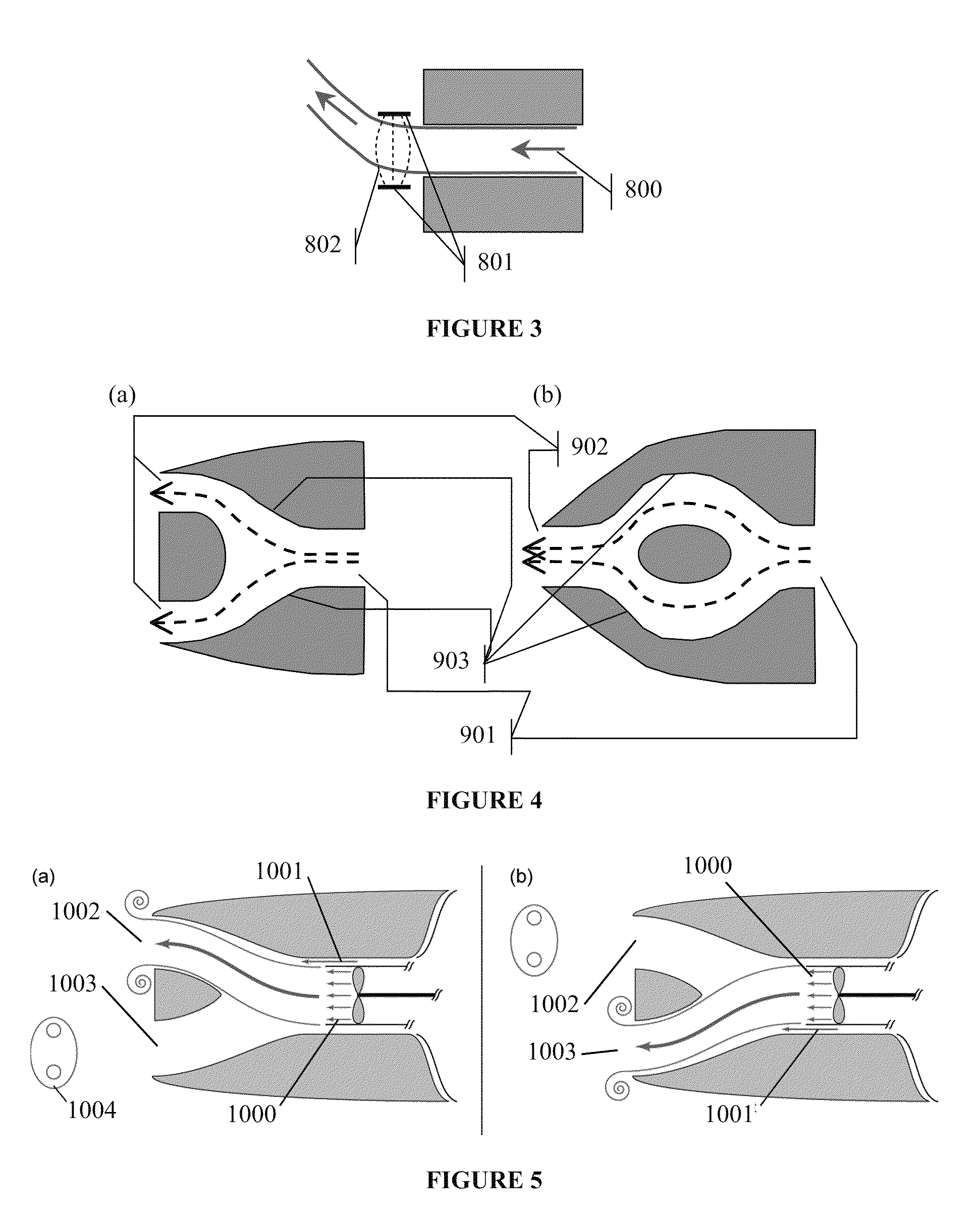
[0013]The present invention includes at least two components: (a) a constant flow (steady) fluid jet produced by any normal method (e.g., propeller) that can be directionally vectored either fluidically (using the Coanda effect, synthetic jets, counter flow, or other means), mechanically (using valves, vanes, or other means), or electromagnetically (using electric and / or magnetic fields to apply side forces to charged particles in the flow) and (b) a nozzle with multiple outlets (orifices) through which the vectored jet may be directed. By alternately vectoring the jet through different outlets, the flow at an outlet will be transient (pulsatile) even though the flow of the primary jet is substantially constant. The purpose of this invention is to produce pulsatile jet flow from a substantially constant flow primary jet in a way that is mechanically efficient, easy to implement, and allows direct control over pulse duration and pulsing frequency. Sufficiently short jet pulses are known to generate compact vortical structures (vortex rings), which have been shown to augment thrust and propulsive efficiency as compared to longer jet pulses and are useful in a variety of marine or aerial propulsion applications. Additionally, the nozzle outlets may be oriented in different directions to provide thrust vectoring, making the invention useful for maneuvering and directional control.

Problems solved by technology

Similarly, Choutapalli (2006) uses a spinning disk with holes to “chop” the flow supply before it reaches the nozzle, resulting in interruptions to the flow and discrete jet pulses exiting the nozzle.
Generating jet pulses by interrupting or inducing oscillations in the primary flow leads to large pressure fluctuations in the flow and / or requires large storage plenums to properly drive the flow.
Using piston-displacement methods to generate jet pulses tends to be inefficient as time and energy are expended retracting the piston and / or refilling the plenum.
The obstruction alternately blocks each of the outlets for a brief period, halting (and hence, pulsing) the flow from that orifice, but no method is provided for controlling the frequency or duration of jet pulses.

Method used


Image

  • Generation of a pulsed jet by jet vectoring through a nozzle with multiple outlets
  • Generation of a pulsed jet by jet vectoring through a nozzle with multiple outlets
  • Generation of a pulsed jet by jet vectoring through a nozzle with multiple outlets

Examples


Embodiment Construction

[0025]While the making and using of various embodiments of the present invention are discussed in detail below, it should be appreciated that the present invention provides many applicable inventive concepts that can be embodied in a wide variety of specific contexts. The specific embodiments discussed herein are merely illustrative of specific ways to make and use the invention and do not delimit the scope of the invention.

[0026]To facilitate the understanding of this invention, a number of terms are defined below. Terms defined herein have meanings as commonly understood by a person of ordinary skill in the areas relevant to the present invention. Terms such as “a”, “an” and “the” are not intended to refer to only a singular entity, but include the general class of which a specific example may be used for illustration. The terminology herein is used to describe specific embodiments of the invention, but their usage does not delimit the invention, except as outlined in the claims.

[...


PUM


Abstract

A method of producing a pulsatile jet flow from a substantially constant flow primary jet in a way that is mechanically efficient, easy to implement, and allows direct control over pulse duration and pulsing frequency is disclosed herein. The invention includes at least two components: (a) a constant flow fluid jet produced by any normal method (e.g., propeller) that can be directionally vectored fluidically, mechanically, or electromagnetically and (b) a nozzle with multiple outlets (orifices) through which the vectored jet may be directed. By alternately vectoring the jet through different outlets, a transient (pulsatile) flow at an outlet is obtained even with a substantially constant primary jet flow. Additionally, the nozzle outlets may be oriented in different directions to provide thrust vectoring, making the invention useful for maneuvering, directional control, etc.

Description

CROSS-REFERENCE TO RELATED APPLICATIONS[0001]This application claims priority to U.S. Provisional Application Ser. No. 61 / 162,552, filed Mar. 23, 2009, which is incorporated herein by reference in its entirety.TECHNICAL FIELD OF THE INVENTION[0002]The present invention relates in general to the field of jet propulsion and thrust vectoring, and more particularly, to devices and methods that provide pulsatile jet flow from a constant jet flow.STATEMENT OF FEDERALLY FUNDED RESEARCH[0003]None.BACKGROUND OF THE INVENTION[0004]Without limiting the scope of the invention, its background is described in connection with pulsatile jet flow.[0005]Pulsed jets have found application in a variety of situations ranging from erosion and breaking of solid components in drilling applications (e.g., U.S. Pat. Nos. 4,607,792, 4,681,264, and 4,389,071) to propulsion. In studies related to propulsion, results for fixed / tethered jets have shown that jet pulsation may be used to augment thrust over equival...

Claims


Application Information

Patent Timeline
IPC IPC(8): B05B17/04B05B1/08
CPCB63H25/46E02F3/9206F15D1/08F02K9/28F02K9/82F02K1/008F02K1/002F02K1/28
Inventor KRUEGER, PAUL S.
Owner SOUTHERN METHODIST UNIVERSITY
Learn More