
Method for controlling a cooking point of a gas oven and device

Inactive Publication Date: 2010-09-23
E G O ELEKTRO GERAETEBAU GMBH
View PDF11 Cites 23 Cited by
  • Summary
  • Abstract
  • Description
  • Claims
  • Application Information

AI Technical Summary

Benefits of technology

[0006]It is provided that, as described above, at the cooking point there is a pan detection, by means of which the gas burner is switched off or a corresponding gas valve on the gas burner is closed when the pan is removed or when the pan detection establishes this. For this purpose, the pan detection may advantageously be formed in the customary way that is known in principle, with capacitive, optical or mechanical systems being suitable in particular. Furthermore, the pan detection together with a control of the cooking point or the gas burner or the gas valve thereof, in particular together with an ignition device for the flame, brings about the effect that the pan detection detects when a pan that has previously been removed is re-placed onto the cooking point. It then reactivates the gas burner by igniting the gas burner and / or opening the gas valve, in order that the cooking process is therefore continued as it were of its own accord after the pan is placed on again.
[0018]The output of a signal, in particular an acoustic signal, before the ignition of the gas burner may have the advantage of detecting an object other than a pan has been placed on, for example a cooking spoon or the like, and warning an operator of the imminent ignition of the gas burner. Then, the object inadvertently placed on can be removed again thus avoiding an accident.

Problems solved by technology

This slow increase of the power level proceeds over the aforementioned time delay and may indeed take the few seconds mentioned.
A gas flame with a very small or the smallest possible power level will generally not be sufficient to cause burning of the hands holding the pan placed on.
Therefore, when a pan is placed on again, there is no automatic further operation of the cooking point or automatic switching back on of the gas burner.
In particular, such slow turning off may also mean that, after the pan is removed, said few seconds are waited before the power level is brought down or the gas burner is turned off.
As a result, the gas burner is not switched off unwantedly, which can result due to a malfunctions or the like when a pan is briefly not detected as placed-on.

Method used


Image

  • Method for controlling a cooking point of a gas oven and device
  • Method for controlling a cooking point of a gas oven and device

Examples


Embodiment Construction

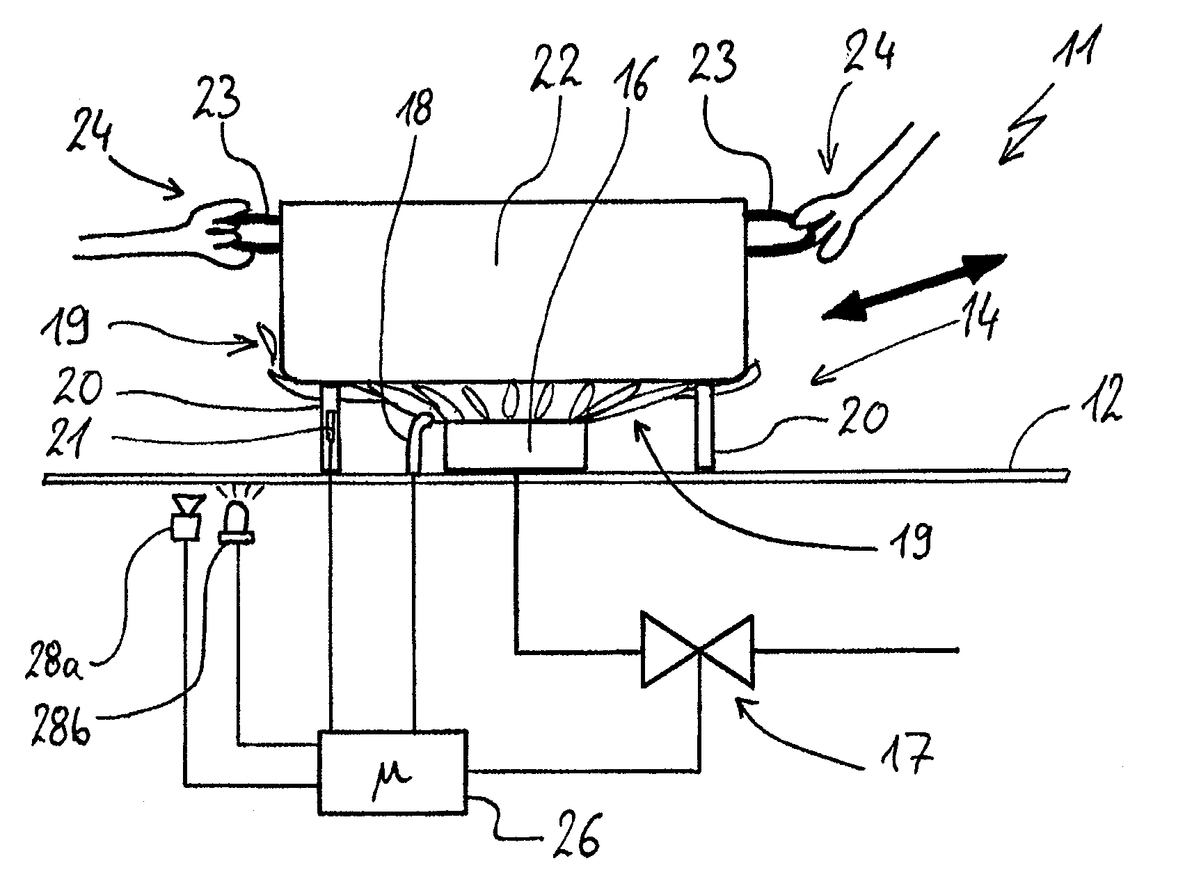
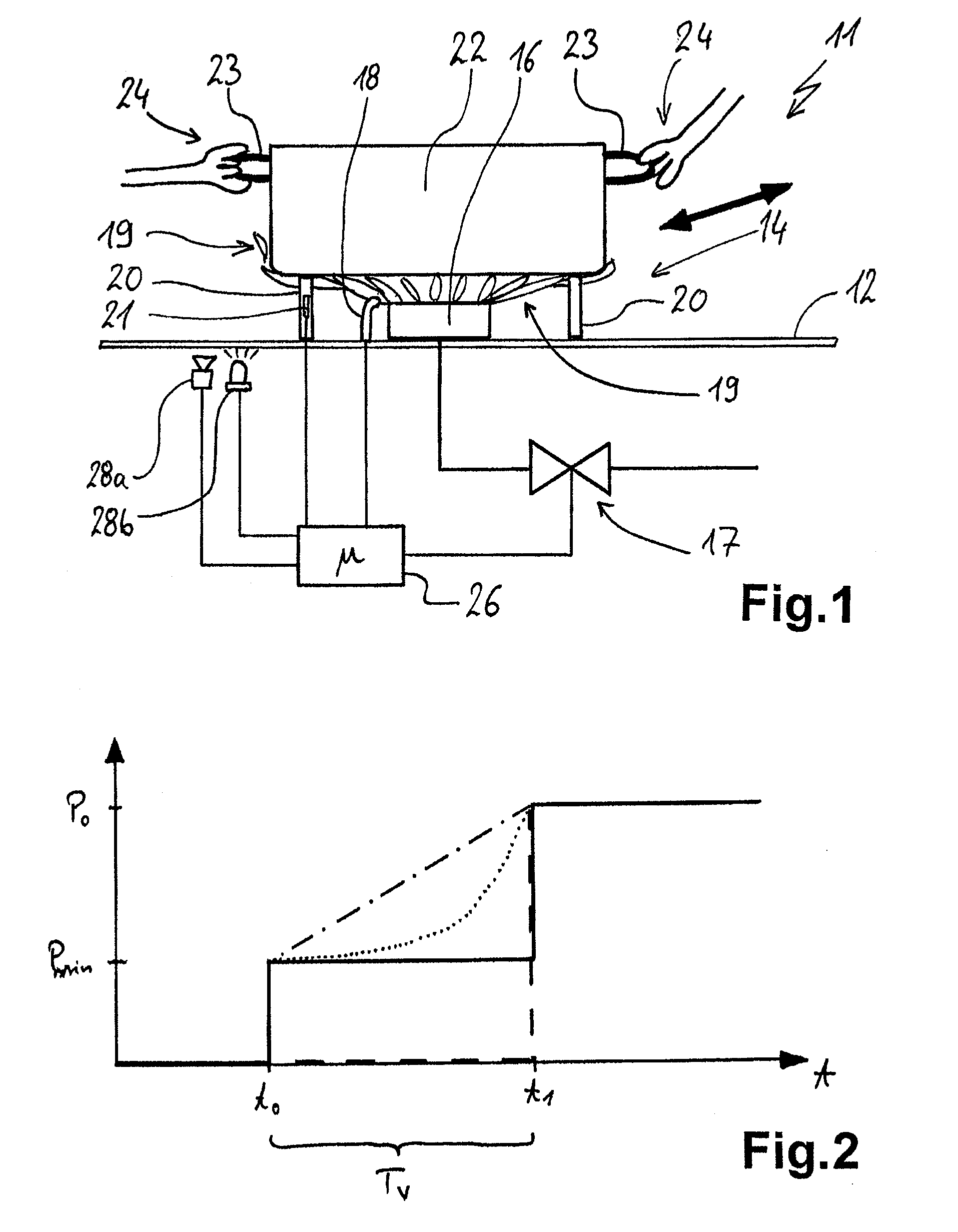
[0023]FIG. 1 illustrates a gas hob 11 as a device according to the invention, on which the method according to the invention can be carried out. The gas hob 11 has a conventional hob panel 12, and a cooking point 14 thereof is illustrated. The cooking point 14 has a conventional gas burner 16 with a gas valve 17 arranged under the hob panel 12, from which valve said burner is supplied. Provided at the gas burner 16 is an ignition device 18 and advantageously a monitoring device (not illustrated) for the gas flames 19. An essentially conventional pan support 20, on which a pan 22 is placed over the gas burner 16 and the cooking point 14, is also provided. This pan support has yet further functions, as still to be explained below. As usual, the pan has side handles 23, which are being gripped by hands 24 of the user, for example because said user has just placed the pan 22 on again.

[0024]Provided on the gas hob 11 is a controller 26, which is connected not only to the gas valve 17, fo...


PUM


Abstract

In one embodiment, a method for operating a cooking point with a gas burner of a gas hob is disclosed in which pan detection is provided for switching off the gas burner when the pan is removed, wherein the pan detection unit can detect the re-placement of a removed pan onto the cooking point and then cause a further operation of the gas burner by igniting the gas burner. When the gas burner is ignited after re-placement of the pan, a power level originally set for the gas burner is only achieved after a time delay, thereby preventing any injury to the user.

Description

CROSS REFERENCE TO RELATED APPLICATIONS[0001]This application claims priority to German Application Number 10 2009 014 570.2, filed on Mar. 17, 2009, the contents of which are incorporated by reference for all that it teaches.FIELD OF THE INVENTION[0002]The invention relates to a method for operating a gas burner at a cooking point, as used in a gas hob. Similarly, the invention relates to a corresponding device.BACKGROUND OF THE INVENTION[0003]There are known hobs with pan detection at a cooking point, the pan detection detecting whether a pan has been placed on or removed. With the removal of the pan, the cooking point is switched off, but a power level (i.e., gas output level) that has been set continues to be maintained. If a pan is then placed on again, the burner ignites immediately and, on account of the pressure conditions in the gas system and the delay of the igniting process, a briefly larger gas flame may occur, even reaching to beyond the handles of the pan. The gas fla...

Claims


Application Information

Patent Timeline
IPC IPC(8): F23N5/00F24C3/12
CPCF24C3/126
Inventor BAIER, MARTIN
Owner E G O ELEKTRO GERAETEBAU GMBH
Learn More