Technique for aggregating an energy service

a technology for aggregating energy and services, applied in the field of energy service aggregation, can solve the problems of not being able to offer the same quality of service to participants, not being able to reasonably expect that a participant bid up to 24 hours in advance of a desired service, etc., to achieve the effect of facilitating the calculation of purchase prices and reducing energy demand

Active Publication Date: 2010-09-23
XEROX CORP
View PDF15 Cites 13 Cited by
  • Summary
  • Abstract
  • Description
  • Claims
  • Application Information

AI Technical Summary

Benefits of technology

[0012]Note that the purchase price may be a minimum price in a range of prices. Moreover, the energy service may include: a demand response in which the participants agree to reduce energy demand, a commitment by the participants to provide power, and/or a commitment by participants to provide ancillary power services.
[0013]A wide variety of information and formats may be included in the supply-function approximation. For example, the supply-function approximation may include a tangent to the supply function of the participant at the probe price. Alternatively or additionally, the supply-function approximation may include a difference equation, a differential equation and/or a finite state machine. In some embodiments, the supply-function approx

Problems solved by technology

However, the participants may not be able to offer the same quality of service that an aggregator needs to provide to the ISO.
As a consequence, it may not be practical for the participants to interact with an aggregator using the same mechanism that the aggregator uses to interact with the ISO.
For example, it may not be reasonable to expect that a participant bid up to 24 hours in advance of a desired service, such as a power reduction or being on standby for power reduction (which is the demand side equivalent to spinning reserve).
Typically, residential customers or small businesses are not able to predict their load 24 hours in advance.
Consequently, they may not be willing to commit to a future reduction with high reliability.
In addition to the incre

Method used


Image

  • Technique for aggregating an energy service
  • Technique for aggregating an energy service
  • Technique for aggregating an energy service

Examples


Embodiment Construction

[0026]The following description is presented to enable any person skilled in the art to make and use the disclosure, and is provided in the context of a particular application and its requirements. Various modifications to the disclosed embodiments will be readily apparent to those skilled in the art, and the general principles defined herein may be applied to other embodiments and applications without departing from the spirit and scope of the present disclosure. Thus, the present disclosure is not intended to be limited to the embodiments shown, but is to be accorded the widest scope consistent with the principles and features disclosed herein.

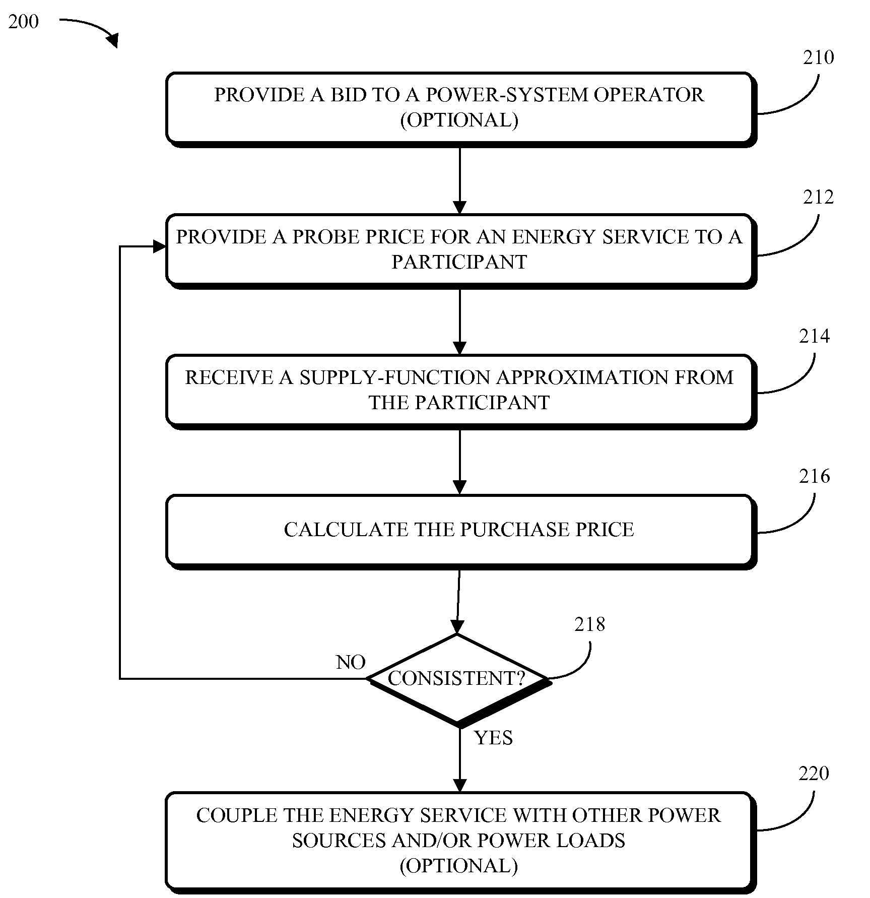
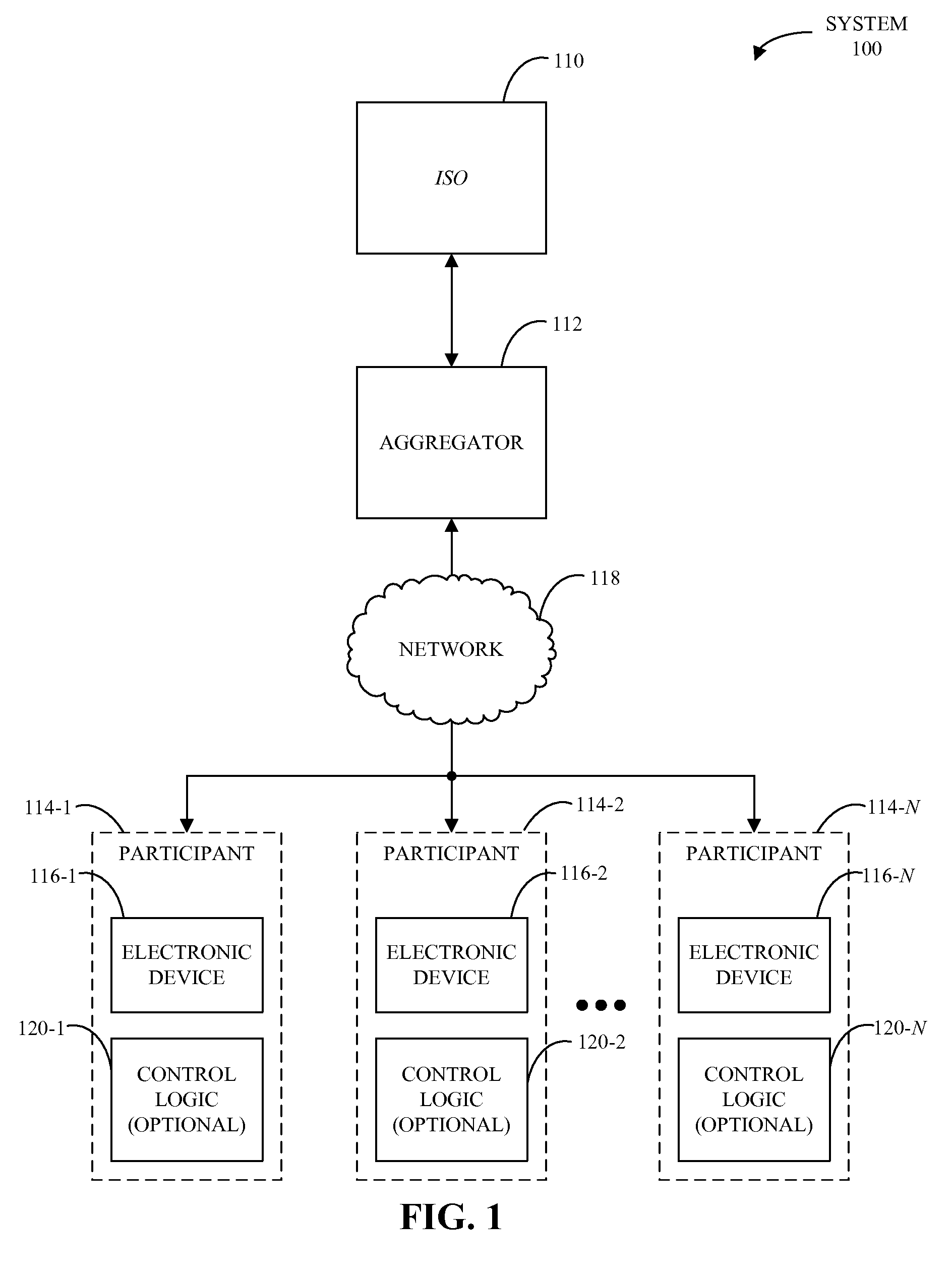
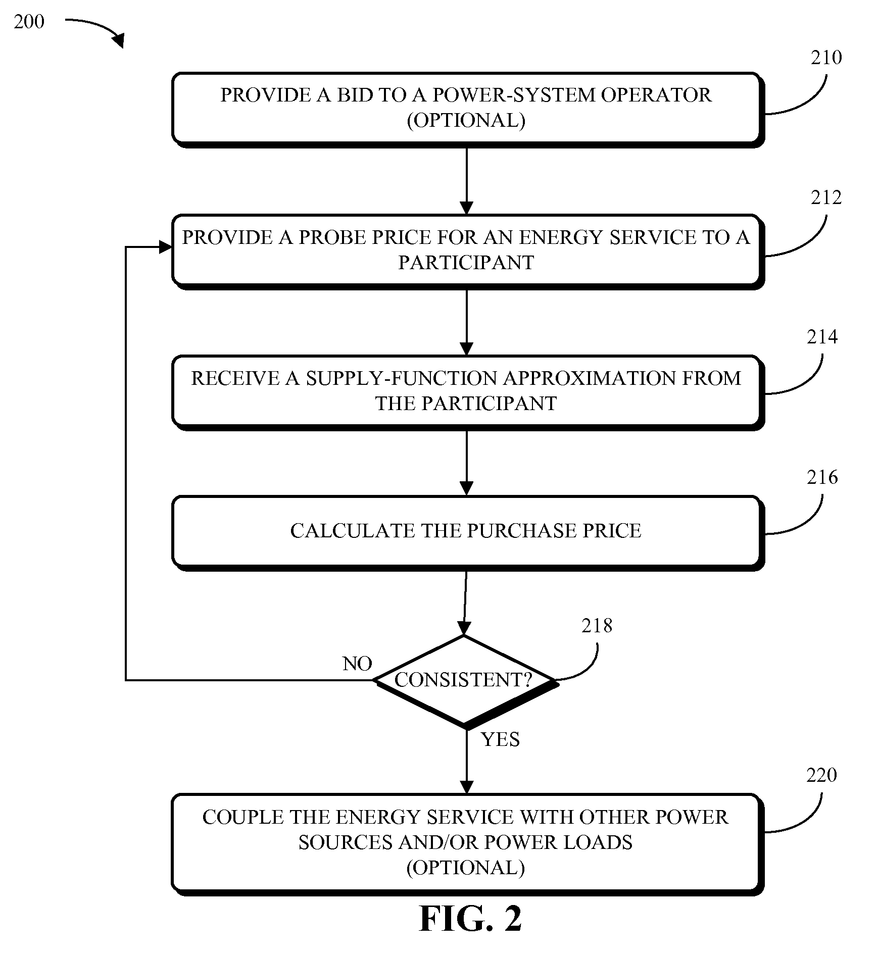
[0027]Embodiments of a system, a method, and a computer-program product (e.g., software) for aggregating an energy service from a number of participants for use by a power-system operator is described. This aggregation may be performed by an aggregator, which is between the participants and the power-system operator. In particular, the aggre...


PUM


Abstract

Embodiments of a system, a method, and a computer-program product (e.g., software) for aggregating an energy service from a number of participants for use by a power-system operator is described. This aggregation may be performed by an aggregator, which is between the participants and the power-system operator. In particular, the aggregator may use an embedded economic mechanism to calculate a price that matches supply (or cutback) of power and/or load from the participants with a desired supply of the power-system operator. Because the aggregator typically does not know the participants' exact propensity to respond as a function of price (supply function), the aggregator calculates the purchase price using one or more iterations in which an initial probe price is provided to the participants, and the participants respond with supply-function approximations that are valid in proximity to the current probe price.

Description

BACKGROUND[0001]1. Field[0002]The present disclosure relates to techniques for aggregating one or more participants in a power system in order to provide an energy service. More specifically, the present disclosure relates to exchanging price points and approximations to supply functions that facilitate aggregation of the one or more participants in order to provide the energy service.[0003]2. Related Art[0004]In traditional electricity markets, economic mechanisms are frequently used to arrive at accurate incentives and to dispatch services. For example, an operator of a power system, such as an independent system operator (ISO), may request bids up to 24 hours in advance of a desired service. In response to the request, one or more suppliers, such as a power plant, may bid to supply power or ancillary services (such as regulation, load following, spinning reserve, non-spinning reserve, replacement reserve and / or other services that help maintain power system stability in response ...

Claims


Application Information

Patent Timeline
IPC IPC(8): G06Q50/00G06Q40/00
CPCG06Q10/06G06Q40/04G06Q50/00Y04S50/00G06Q50/06Y04S50/16
Inventor PAPAVASILIOU, ANTHONYHINDI, HAITHAM ALI SALEMGREENE, DANIEL H.
Owner XEROX CORP
Why Eureka
Try Eureka