Sliding Pivotable Door

a technology of sliding pivoting and sliding doors, which is applied in the direction of doors/windows, door/window fittings, wing arrangements, etc., can solve the problems of disadvantageous guiding rails in the upper and/or lower guiding areas, and disadvantageous driving door leaf arrangement in a superimposed sliding pivoting movement by the guiding rails, so as to improve the sliding pivoting movement

Inactive Publication Date: 2010-09-30
DORMA GMBH & CO KG
View PDF23 Cites 38 Cited by
  • Summary
  • Abstract
  • Description
  • Claims
  • Application Information

AI Technical Summary

Benefits of technology

[0006]It is an object of the present invention to provide a sliding pivotable door that overcomes the disadvantages of the aforementioned state-of-the-art and provides an improved sliding pivoting movement for the door leaf arrangement.
[0033]A redundant motor winding body results in higher operational safety of the sliding pivotable door when carrying out the opening movement. This so-called 2D-technology allows for electrical independent operation circuits, such that, in the event of an electrical failure of the first motor winding body, the existing redundant second motor winding body can still perform an opening movement of the door leaf arrangement and is preferably operated by a likewise redundant power circuit.
[0034]The present invention is furthermore directed to a method for an opening and closing operation of the sliding pivotable door. In this case, the pivoting movement of the door leaf arrangement can be executed independently from the linear movement of the second door leaf along the first door leaf. In this case, an embodiment of the sliding pivotable door is to be considered which has at least two electrical drive units, wherein the first electrical drive unit is provided exclusively for driving the pivoting movement and the second electrical drive unit is exclusively provided for driving the telescopic movement of the door leaves of the respective door leaf arrangement towards each other. This results in the advantage that the start of the pivoting movement and the start of the telescopic movement are not coupled to each other with regard to the timely sequence. As a consequence, the pivoting movement and the telescopic movement can be performed synchronously with regard to each other such that the two movements start at substantially the same time.

Problems solved by technology

However, the required guiding rails in the upper and / or lower guiding areas are disadvantageous.
Furthermore, driving the door leaf arrangement in a superimposed sliding-pivoting movement by the guiding rails is disadvantageous, if the sliding pivotable door is not to be exclusively manually operated.

Method used


Image

  • Sliding Pivotable Door
  • Sliding Pivotable Door
  • Sliding Pivotable Door

Examples


Embodiment Construction

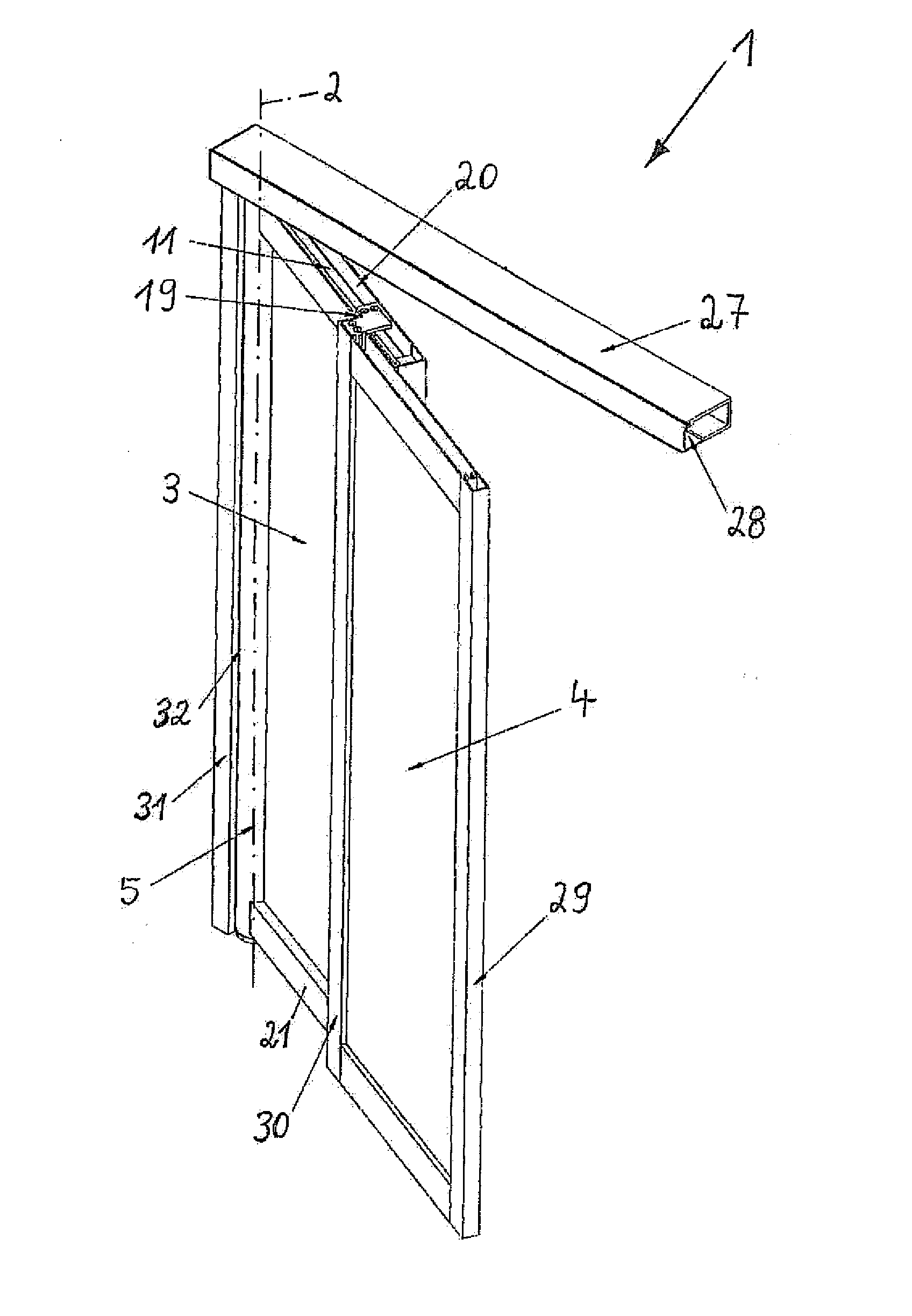
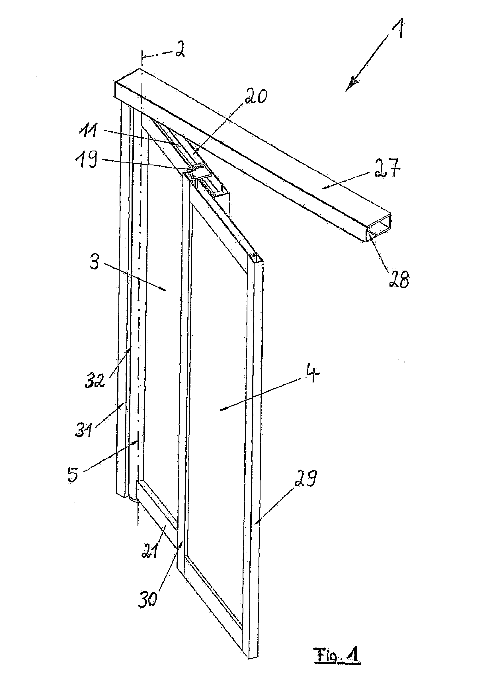
[0055]In a perspective view, FIG. 1 shows an embodiment of the inventive sliding pivotable door 1. The sliding pivotable door 1 may be accommodated in the wall or in the facade of a building such that the shown pivot axis 2 extends vertically. The frame of the sliding pivotable door 1 is formed by a vertical supporting member 31, which, may be formed by a wall of a building. A transverse beam 27 is shown at the top side, which, as a hollow body, is closable by a transverse beam enclosure 28 at the front side. The sliding pivotable door 1 has a pivoting column 5 which is parallel and adjacent to the vertical supporting member 31.

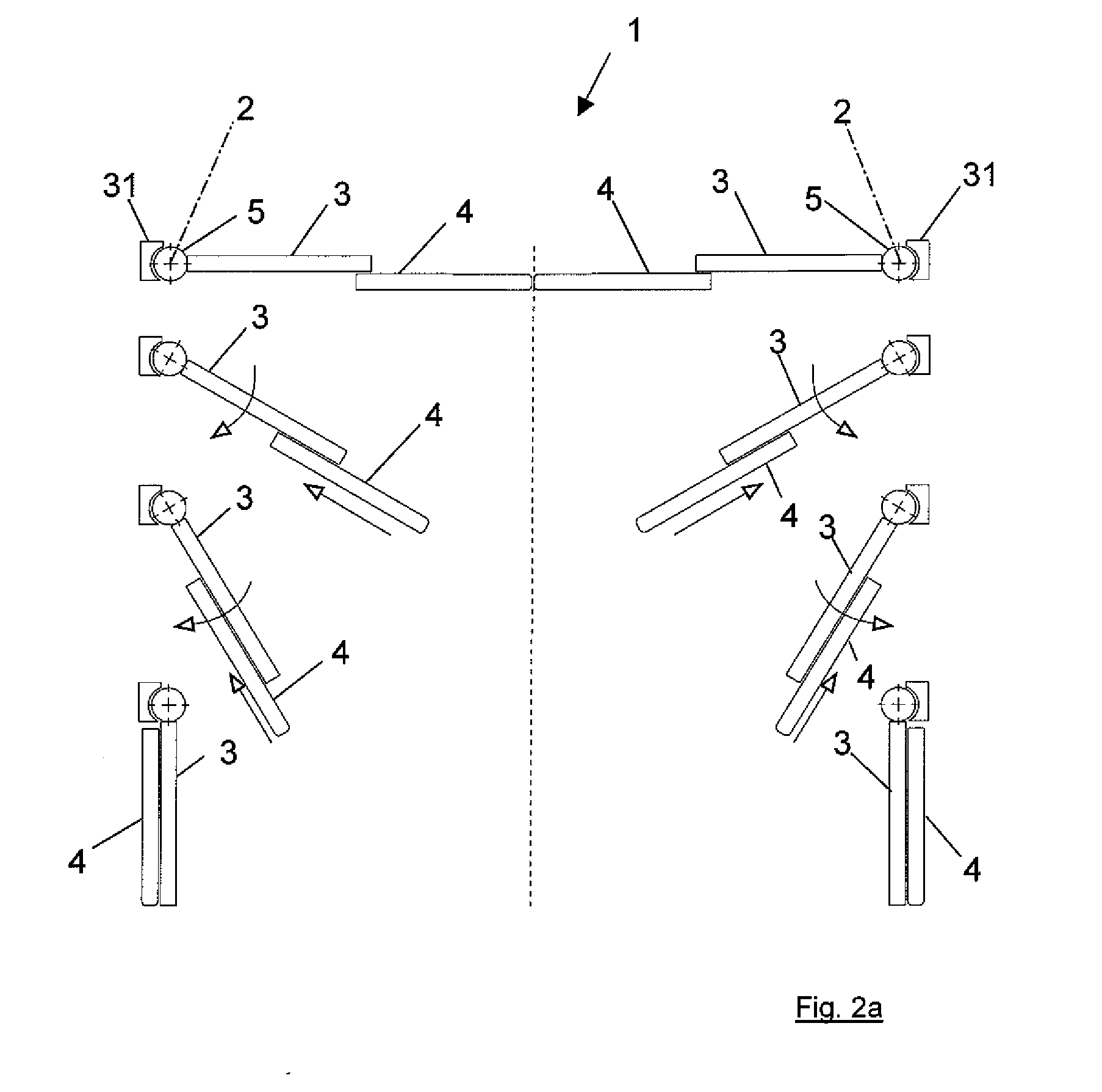
[0056]A first door leaf 3 is disposed to be pivotable about the pivot axis 2 such that the first door leaf 3 exclusively executes a pivoting movement about the pivot axis 2. The second door leaf 4 is accommodated and linearly guided at the first door leaf 3, such that the second door leaf 4 performs the pivoting movement together with the first door leaf 3 an...


PUM


Abstract

A sliding pivotable door as well as a method for operating a sliding pivotable door with at least one door leaf arrangement, which is accommodated to be pivotable about an associated pivot axis. The door leaf arrangement has a first door leaf, which is pivotable about the pivot axis, and at least one second door leaf is provided, which is linearly guided at the first door leaf and, together with the first door leaf, is pivotable about the pivot axis.

Description

BACKGROUND OF THE INVENTION [0001]1. Field of the Invention[0002]The present invention relates to a sliding pivotable door with at least one door leaf arrangement that is accommodated to be pivotable about an associated pivot axis. The present invention relates furthermore to a method for the opening and closing operation of the sliding pivotable door.[0003]2. Description of the Related Art[0004]A sliding pivotable door with a door leaf arrangement, accommodated to be pivotable about an associated pivot axis, is known from DE 196 00 444 A1. For guiding the sliding-pivoting movement of the door leaf arrangement, upper and / or lower guiding rails are required. The guiding rails, by which the door leaf arrangement is both guided and held, may be incorporated in the ceiling or in the floor of a room. This results in a folding movement, by which the door leaf arrangement achieves a pivoting range, which is smaller than the required pivoting range, determined by an exclusive pivoting movem...

Claims


Application Information

Patent Timeline
Patent Type & Authority Applications(United States)
IPC IPC(8): E05F15/18E06B3/50E05D15/48E05F15/60
CPCE05D15/58E05D2015/585E05Y2800/122E05Y2800/262E05F15/652E05Y2900/00E05F15/614E05F15/643E05Y2900/132E05F17/00E05Y2201/62E05F15/63
Inventor LIEBSCHER, ARNEGLANZ, MICHAELFINKE, ANDREASWILDFORSTER, THOMAS
Owner DORMA GMBH & CO KG
Why Eureka
Try Eureka