Adjustable igniter mount

a technology of gas turbine combustor and mount, which is applied in the direction of gas turbine plants, machines/engines, jet propulsion plants, etc., can solve the problems of limited movement of the igniter, the inability of the prior art igniter and plate to adjust the position of the igniter within the combustor,

Inactive Publication Date: 2010-09-30
ALSTOM TECH LTD
View PDF14 Cites 15 Cited by
  • Summary
  • Abstract
  • Description
  • Claims
  • Application Information

AI Technical Summary

Benefits of technology

[0005]In accordance with the present invention, there is provided a novel configuration for an ignition system and way for adjusting an igniter relative to a combustor. The ignition system provides a way in which an igniter location can be adjusted relative to a combustor.

Problems solved by technology

However, embodiments of the prior art igniter and plate have little capability to adjust the position of the igniter within the combustor.
However, movement of the igniter is limited to the rotational movement caused by the pivoting ball joint 106.

Method used


Image

  • Adjustable igniter mount
  • Adjustable igniter mount
  • Adjustable igniter mount

Examples


Embodiment Construction

[0019]The subject matter of the present invention is described with specificity herein to meet statutory requirements. However, the description itself is not intended to limit the scope of this patent. Rather, the inventors have contemplated that the claimed subject matter might also be embodied in other ways, to include different components, combinations of components, steps, or combinations of steps similar to the ones described in this document, in conjunction with other present or future technologies.

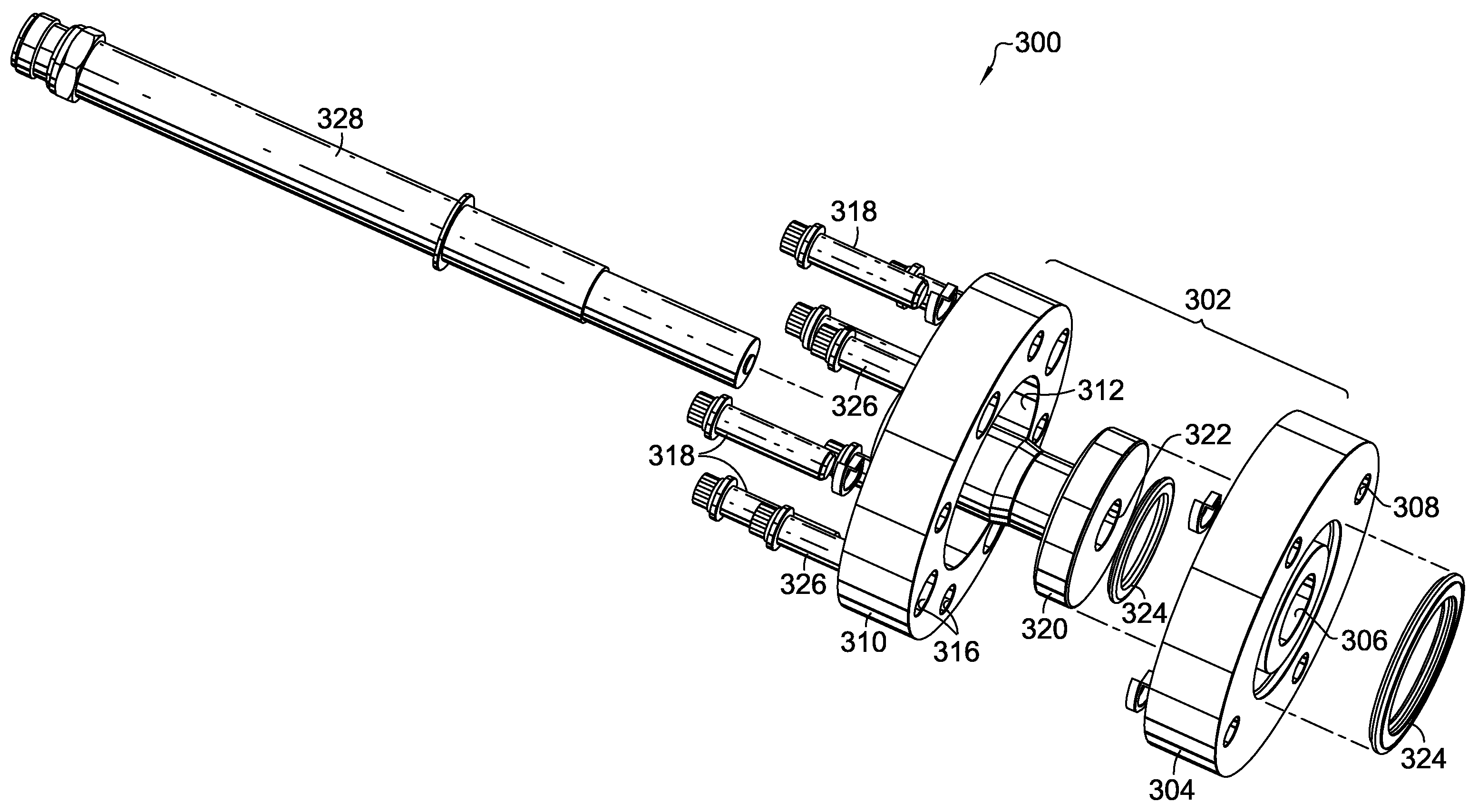
[0020]Referring to FIGS. 3 and 4, an embodiment of the present invention is shown in detail. The ignition system 300 comprises a base assembly 302 having a first base plate 304 with a first central opening 306 extending through the first plate 304 and having a first plurality of through holes 308 and a plurality of threaded holes (not shown) spaced in between the through holes 308. The base assembly 302 also comprises a second base plate 310 which has a second central opening 312 th...


PUM


Abstract

An ignition assembly for providing increased movement of an igniter within a combustor is provided. The ignition assembly includes a base assembly having a first base plate, a second base plate, and a positioning plate, where the positioning plate contains an igniter and is capable of adjusting in an axial and/or circumferential direction relative to the combustor.

Description

TECHNICAL FIELD[0001]The present invention generally relates to an ignition system for a gas turbine combustor. More specifically, the ignition system includes a base capable of providing planar adjustment of an igniter position within a combustor.BACKGROUND OF THE INVENTION[0002]Gas turbine engines operate to produce mechanical work or thrust. Specifically, land-based gas turbine engines typically have a generator coupled thereto for the purposes of generating electricity. A gas turbine engine comprises an inlet that directs air to a compressor section which has stages of rotating compressor blades spaced between stages of stationary vanes. As the air passes through the compressor, the pressure of the air increases. The compressed air is then directed into one or more combustors where fuel is injected into the compressed air and the mixture is ignited. The hot combustion gases are then directed from the combustion section to a turbine section. As the hot combustion gases pass throu...

Claims


Application Information

Patent Timeline
Patent Type & Authority Applications(United States)
IPC IPC(8): F02C7/266
CPCF02C7/266
Inventor SULLIVAN, DANIEL J.
Owner ALSTOM TECH LTD
Why Eureka
Try Eureka