Systems for weighing a pulled object having a changing weight

a technology of pulling object and weighing system, which is applied in the direction of instruments, crystal growth process, force/torque/work measurement apparatus, etc., can solve the problem of not measurable change in weight of ingot, ill-suited for determining the diameter of a growing silicon ingot, and known systems use more expensive and less accurate systems for determining the diameter

Active Publication Date: 2010-09-30
GLOBALWAFERS CO LTD
View PDF11 Cites 7 Cited by
  • Summary
  • Abstract
  • Description
  • Claims
  • Application Information

AI Technical Summary

Benefits of technology

[0007]One aspect is an apparatus for measuring the weight of an object while pulling the object upward. The apparatus comprises a frame having a vertical axis and a horizontal axis, the vertical axis parallel to an axis along which the object is pulled, the horizontal axis being orthogonal to the vertical axis. A cable coupled to the object. A first cylinder is rotatably connected to the frame and at least a portion of the cable engages a surface of the first cylinder. A second cylinder is rotatably connected to the frame and at least a portion of the cable engages a surface of the second cylinder. An upper arm has a first end, a second end and the upper arm is coupled to the frame. A lower arm is coupled at one end to the first cylinder and at another end to the frame. An actuator is coupled to the upper arm. A force measurement device measures the weight of the object. The force measurement device is coupled to the first cylinder. The actuator is operable to lower and raise the force measurement device, the first cylinder, and the second cylinder. The lower arm substantially restrains the first cylinder from movement parallel to the horizontal axis.

Problems solved by technology

While the density and growth velocity of the ingot are readily determinable to a high degree of accuracy, the rate of change of weight of the ingot is not measurable with a high enough degree of accuracy by previous systems to ensure a correct determination of the ingot diameter.
The inherent inaccuracies of previous force measurement systems described above thus render them ill-suited for determining the diameter of a growing silicon ingot based on the weight of the ingot.
Known systems therefore utilize more costly and less accurate systems for determining the diameter of the growing silicon ingot.
Moreover, orbital and / or pendular motion of the cable can affect the amount of force exerted on the load cell by the cable and thus affect the force measurement.

Method used


Image

  • Systems for weighing a pulled object having a changing weight
  • Systems for weighing a pulled object having a changing weight
  • Systems for weighing a pulled object having a changing weight

Examples


Embodiment Construction

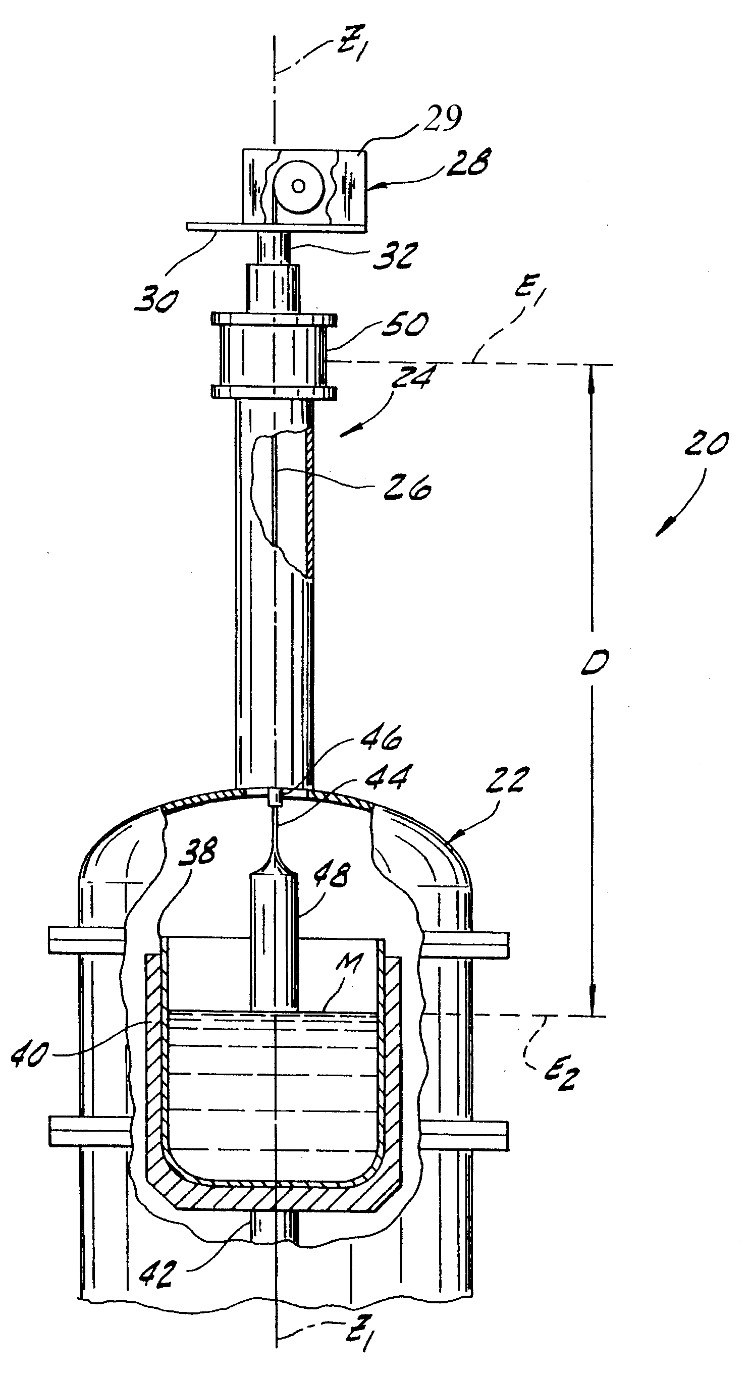
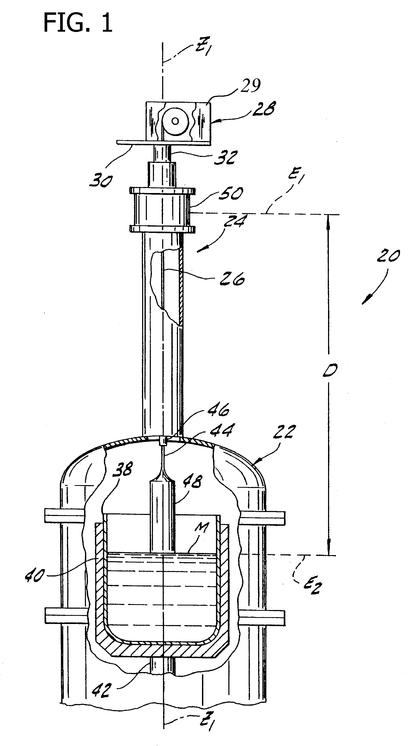
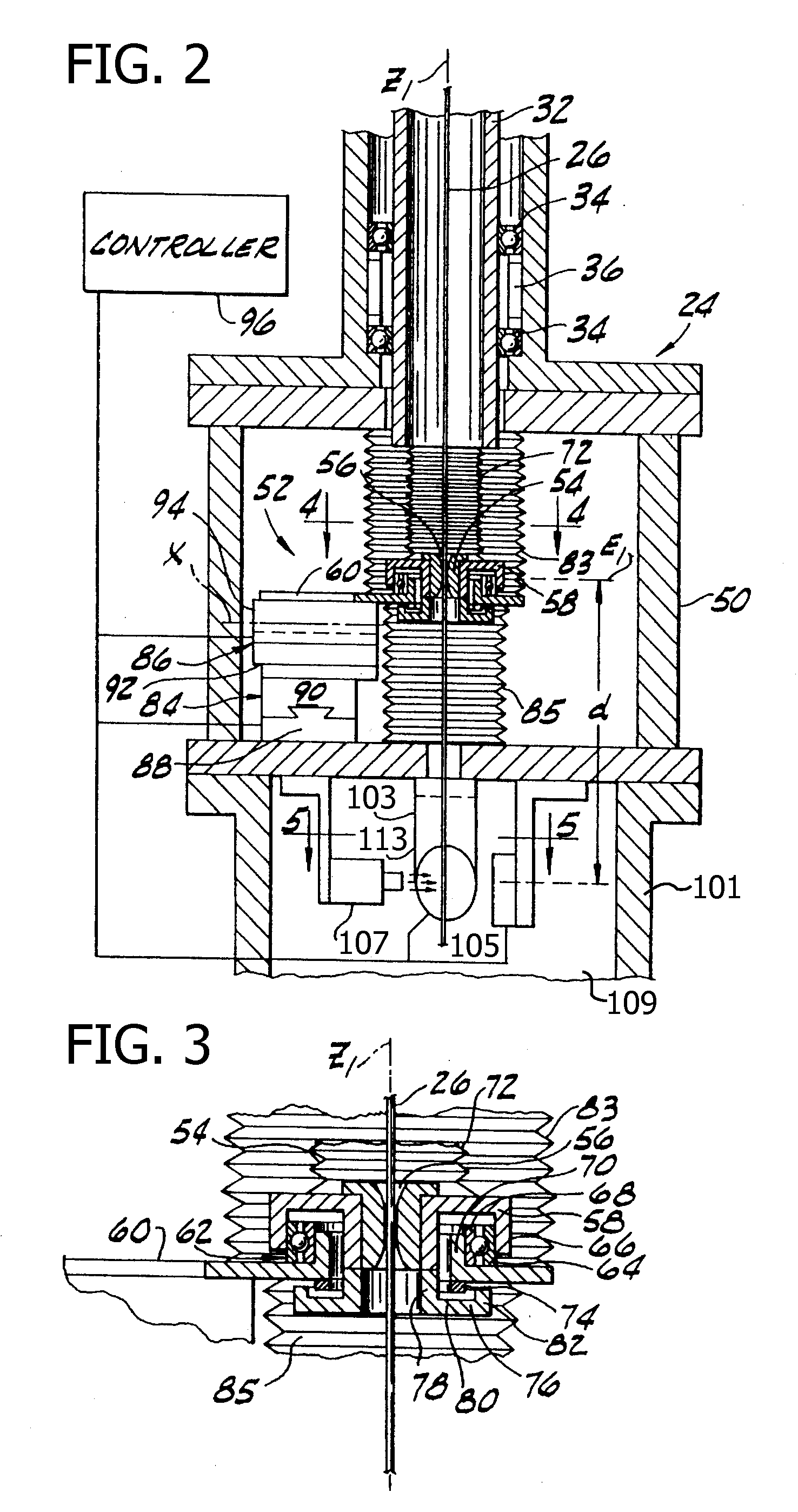
[0050]Referring now to the drawings, and an embodiment shown in FIGS. 1 and 2, a crystal pulling machine of the type which produces monocrystals by the Czochralski method is indicated in its entirety by the reference numeral 20. The crystal pulling machine 20 includes a growth chamber, generally indicated at 22, and an elongate pulling chamber, generally indicated 24, above the growth chamber. A pull cable 26 extends from a crystal lifting mechanism, generally indicated at 28, which operates like a winch to selectively reel in and let out the pull cable. The crystal lifting mechanism 28 is enclosed by a housing 29 and the winch of the crystal lifting mechanism is coupled to the housing 29. The crystal lifting mechanism 28 is securely mounted on a plate 30 which is secured to the top of and rotates with a rotatable shaft 32 (or support). The shaft 32 is coupled to the pulling chamber 24 via suitable bearings 34 (FIG. 2) and may be rotated relative to the pulling chamber by a suitable...


PUM

PropertyMeasurementUnit
frequenciesaaaaaaaaaa
distanceaaaaaaaaaa
yield weightaaaaaaaaaa

Abstract

A system for measuring the weight of an object while pulling the object upward includes a puller having a frame and a cable having a first end coupled to the object and a second end engaging a second cylinder. At least a portion of the cable engages the outer circumferential surface of a first cylinder and the second cylinder. The apparatus also includes an upper arm and an actuator. A force measurement device is coupled to the first cylinder and to the upper arm and measures the weight of the object. The actuator is operable to lower and raise the weight measurement device and the first cylinder. In some embodiments, the position of the cable with respect to the frame may be adjusted by a dampening system or a bushing.

Description

CROSS-REFERENCE TO RELATED APPLICATIONS[0001]This application claims priority to U.S. Provisional Application Nos. 61 / 165,285; 61 / 165,291; 61 / 165,294, all filed Mar. 31, 2009; Application No. 61 / 234,472, filed Aug. 17, 2009; and Application No. 61 / 262,666, filed Nov. 19, 2009.FIELD OF THE DISCLOSURE[0002]The field of the disclosure relates generally to systems for measuring the weight of an object suspended from a cable and, more specifically, to systems for measuring the weight of an object having a changing weight.BACKGROUND[0003]This section is intended to introduce the reader to various aspects of art that may be related to various aspects of the present invention, which are described and / or claimed below. This discussion is believed to be helpful in providing the reader with background information to facilitate a better understanding of the various aspects of the present invention. Accordingly, it should be understood that these statements are to be read in this light, and not ...

Claims


Application Information

Patent Timeline
Patent Type & Authority Applications(United States)
IPC IPC(8): G01L5/04
CPCG01G23/12C30B15/28G01G19/18Y10T117/1004G01L5/04
Inventor KORB, HAROLD
Owner GLOBALWAFERS CO LTD
Why Eureka
Try Eureka