Transmission Device for Work Vehicle

a technology for working vehicles and transmission devices, which is applied in the direction of agricultural machines, brake systems, gearing, etc., can solve the problems of large amount of tillage residue remaining and troublesome subsequent processing work

Active Publication Date: 2010-09-30
KUBOTA LTD
View PDF7 Cites 18 Cited by
  • Summary
  • Abstract
  • Description
  • Claims
  • Application Information

AI Technical Summary

Benefits of technology

[0050]The resulting advantage is the ability to selectively use

Problems solved by technology

The resulting drawback is that when the PTO clutch is disengaged before a vehicle body having a rotary tiller stops, or when the vehicle body starts to travel before the PTO clut

Method used


Image

  • Transmission Device for Work Vehicle
  • Transmission Device for Work Vehicle
  • Transmission Device for Work Vehicle

Examples


first embodiment

Overall Configuration of Work Vehicle

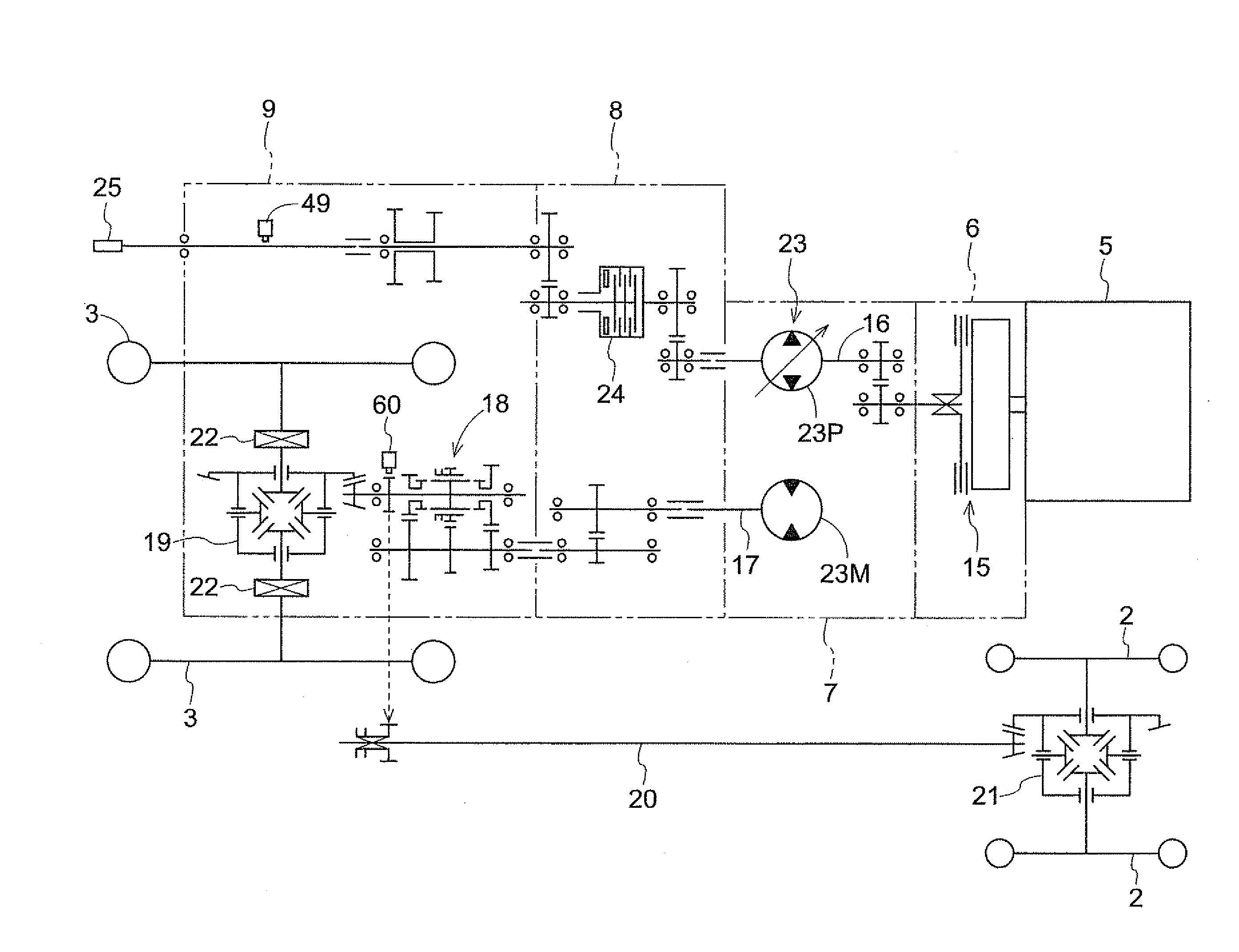
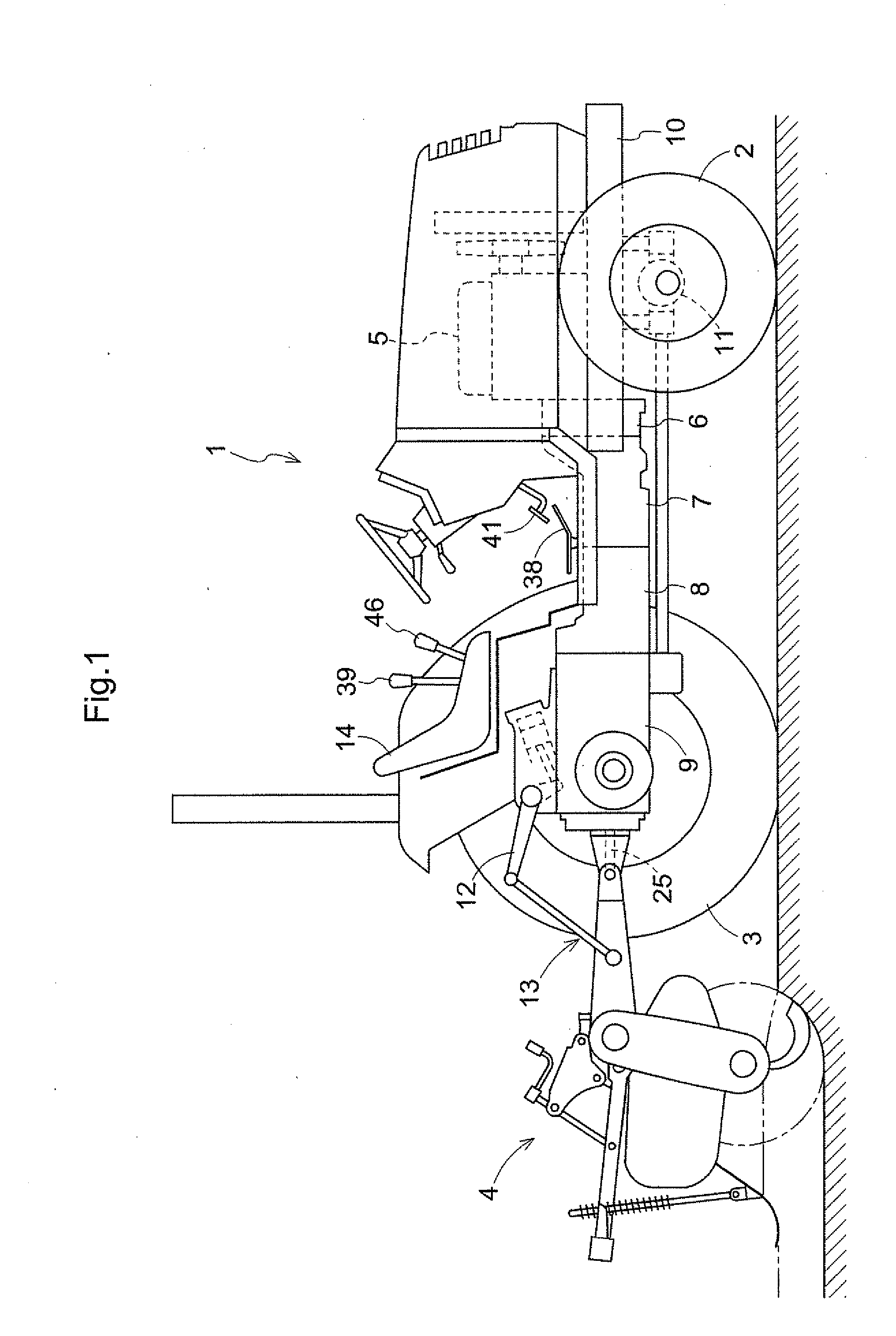
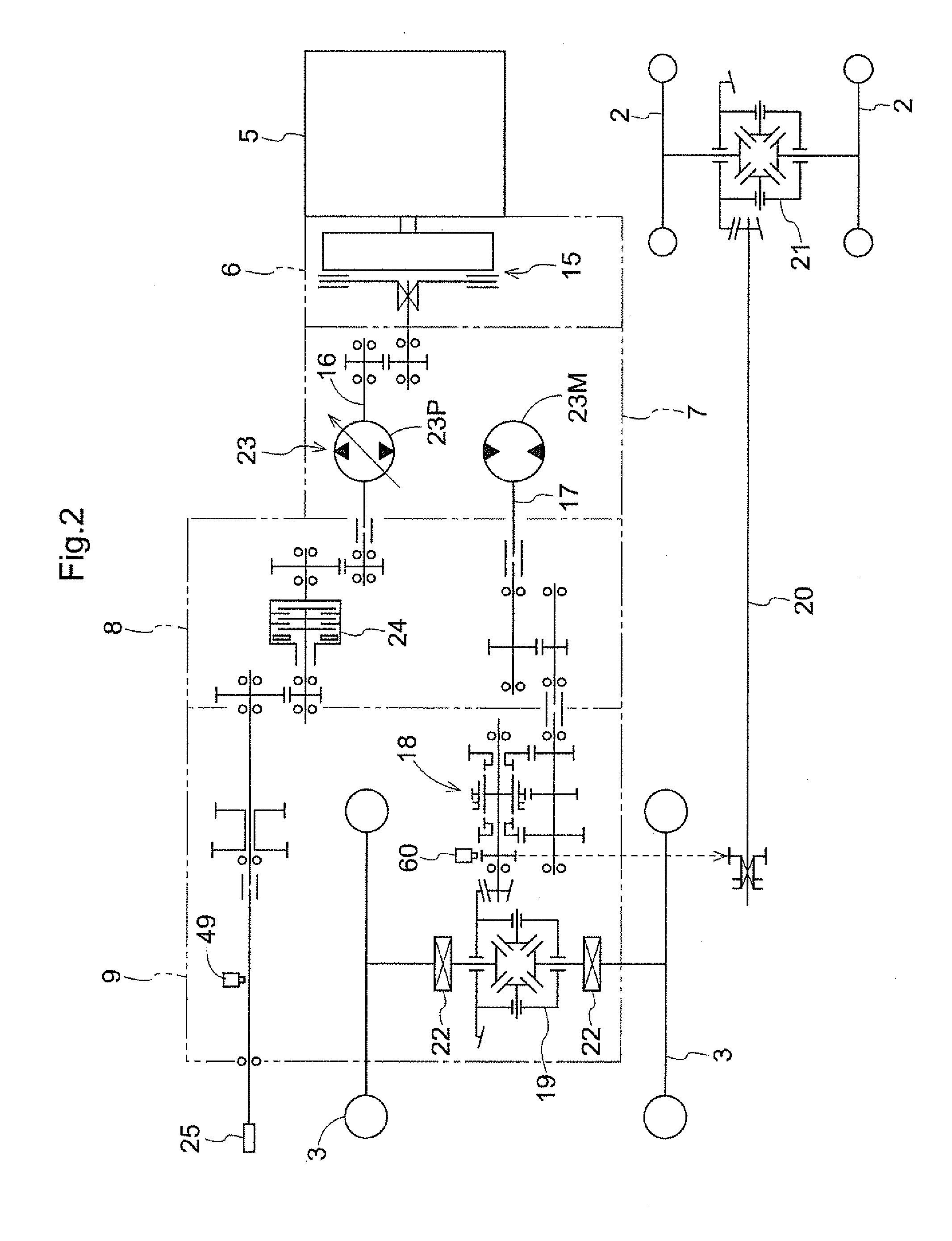
[0064]FIG. 1 shows a tractor configured with a rotary tiller design, which is an example of a work vehicle comprising the transmission device of the present invention.

[0065]This tractor is configured with a rotary tiller 4 raisably and lowerably linked to the rear part of a four-wheel drive tractor frame 1 comprising front wheels 2 and rear wheels 3. The vehicle body of the tractor frame 1 is configured with a mono body design, wherein an engine 5, a primary clutch housing 6, a primary speed change case 7, a mid case 8, and a transmission case 9 are directly coupled in series. A front wheel axle case 11 is rollably supported on a front frame 10 linked to the engine 5, the front wheels 2 are supported to be capable of operating in the steered direction on the left and right of the front wheel axle case 11, and the rear wheels 3 are axially supported on the left and right of the transmission case 9. A link mechanism 13 driven up and down by lift ar...

embodiment 4

Additional Embodiment 4

[0130]The stop operation mechanism is not limited to the hydro static transmission 23, and may also be a gear-based speed change device or a travel clutch.

embodiment 5

Additional Embodiment 5

[0131]The forward / reverse travel detection sensor is not limited to detecting the operating state of the speed change pedal 38, and another possible example includes a work vehicle not having a hydro static transmission 23, or a work vehicle having a hydro static transmission 23 but also having a separate forward / reverse travel speed change device, in which case an arrangement can be adopted in which the operating state of the forward / reverse travel speed change device is detected. It is also possible to adopt an arrangement in which the rotational direction of the vehicle wheel drive axle is detected.


PUM


Abstract

A transmission device for a work vehicle, comprising a travel drive system for transmitting engine power to a travel device; an implement drive system for transmitting engine power to an external power take-off shaft; braking operation tools for a braking operation; a stop operation mechanism provided to the travel drive system and capable of interrupting the transmission of power to the travel device; and a hydraulically operated PTO clutch for interrupting the transmission of power to the external power take-off shaft, the PTO shaft being provided to the implement drive system; wherein
    • the stop operation mechanism and the PTO clutch are linked with the braking operation tools so that the stop operation mechanism is operated to a power transmission stopping position and the PTO clutch is disengaged along with a pressing operation of the braking operation tools, and the PTO clutch is engaged along with a press-releasing operation of the braking operation tools; and an operation timing is set so that the PTO clutch is disengaged after traveling is detected to have stopped when the braking operation tools are operated in the pressing direction, and that the PTO clutch is engaged before traveling is started when the braking operation tools are operated in the press-releasing direction.

Description

BACKGROUND OF THE INVENTION[0001]The present invention relates to a transmission device for a work vehicle comprising a transmission device of a travel drive system for transmitting engine power to a travel device, and also comprising a transmission device of an implement drive system for transmitting engine power to an external power take-off shaft, and further comprising braking operation tools for stopping the traveling of the vehicle body.[0002]Devices having the structure described below have been known in conventional practice as this type of transmission device for a work vehicle.[0003]Specifically, brake pedals as the braking operation tools are pressed, bringing a speed change device for traveling to a stopped state, and a PTO clutch of the implement drive system is operated in a disengaging direction so as to stop the driving of a PTO shaft as well. In the known example of a transmission device for a work vehicle, when tilling work is then restarted, the PTO clutch is auto...

Claims


Application Information

Patent Timeline
IPC IPC(8): F16H37/00B60K17/28
CPCB60K25/00A01B71/02B60K17/28B60T7/00
Inventor INAMORI, TAKUYAMUKAI, HISAOMATSUZAKI, YUSHIUMEMOTO, SUSUMUONO, AKIYOSHIHIWATASHI, AKIRA
Owner KUBOTA LTD
Why Eureka
Try Eureka