Multi-needle sewing machine
a multi-needle, sewing machine technology, applied in sewing machine control devices, embroidering machines, textiles and paper, etc., can solve the problems of increasing the size difficulty in passing threads through the respective tubes, and complicated construction of the multi-needle sewing machine, so as to prevent thread entanglement, compact size, and simple construction
- Summary
- Abstract
- Description
- Claims
- Application Information
AI Technical Summary
Benefits of technology
Problems solved by technology
Method used
Image

Examples
first example
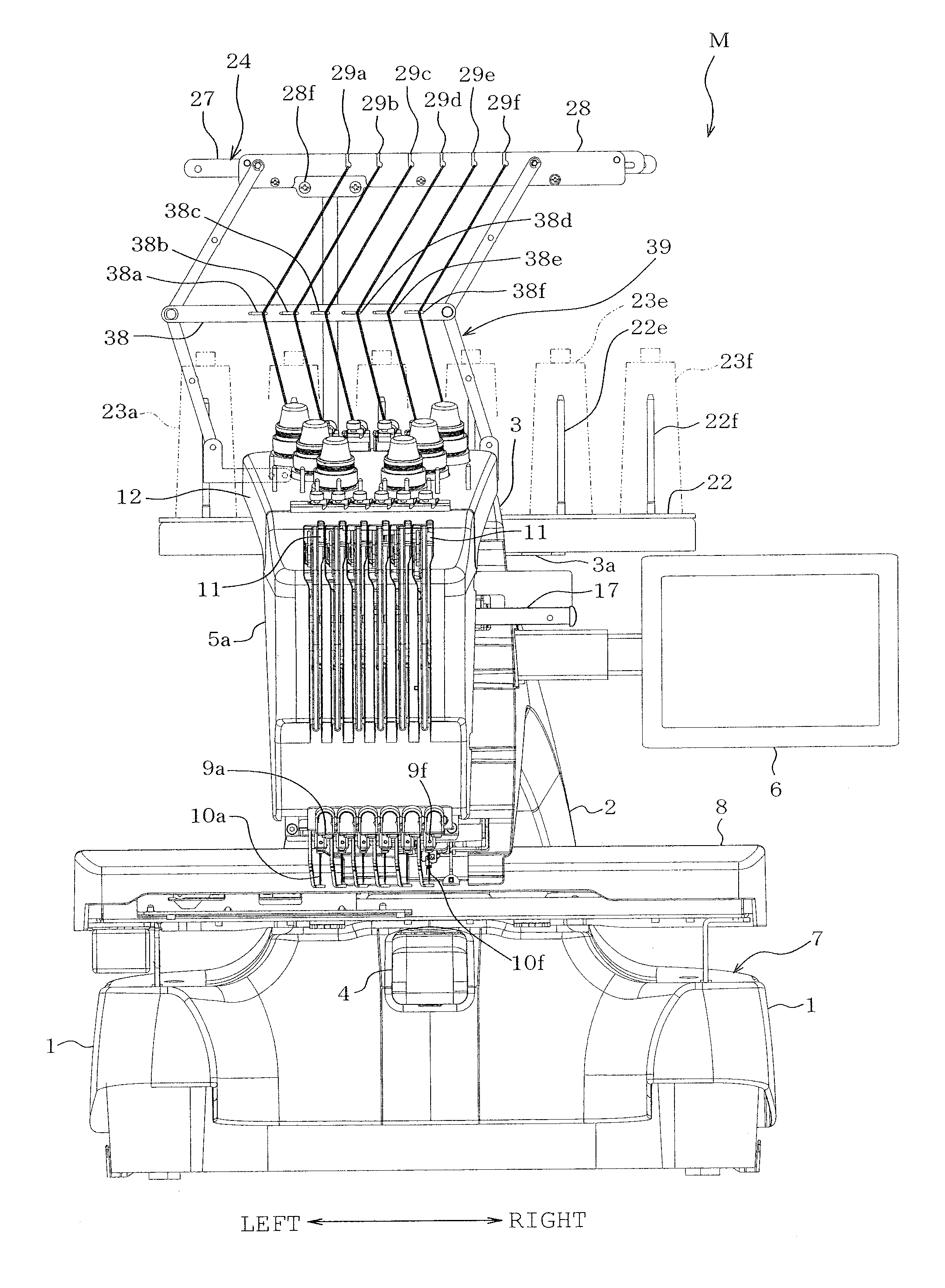
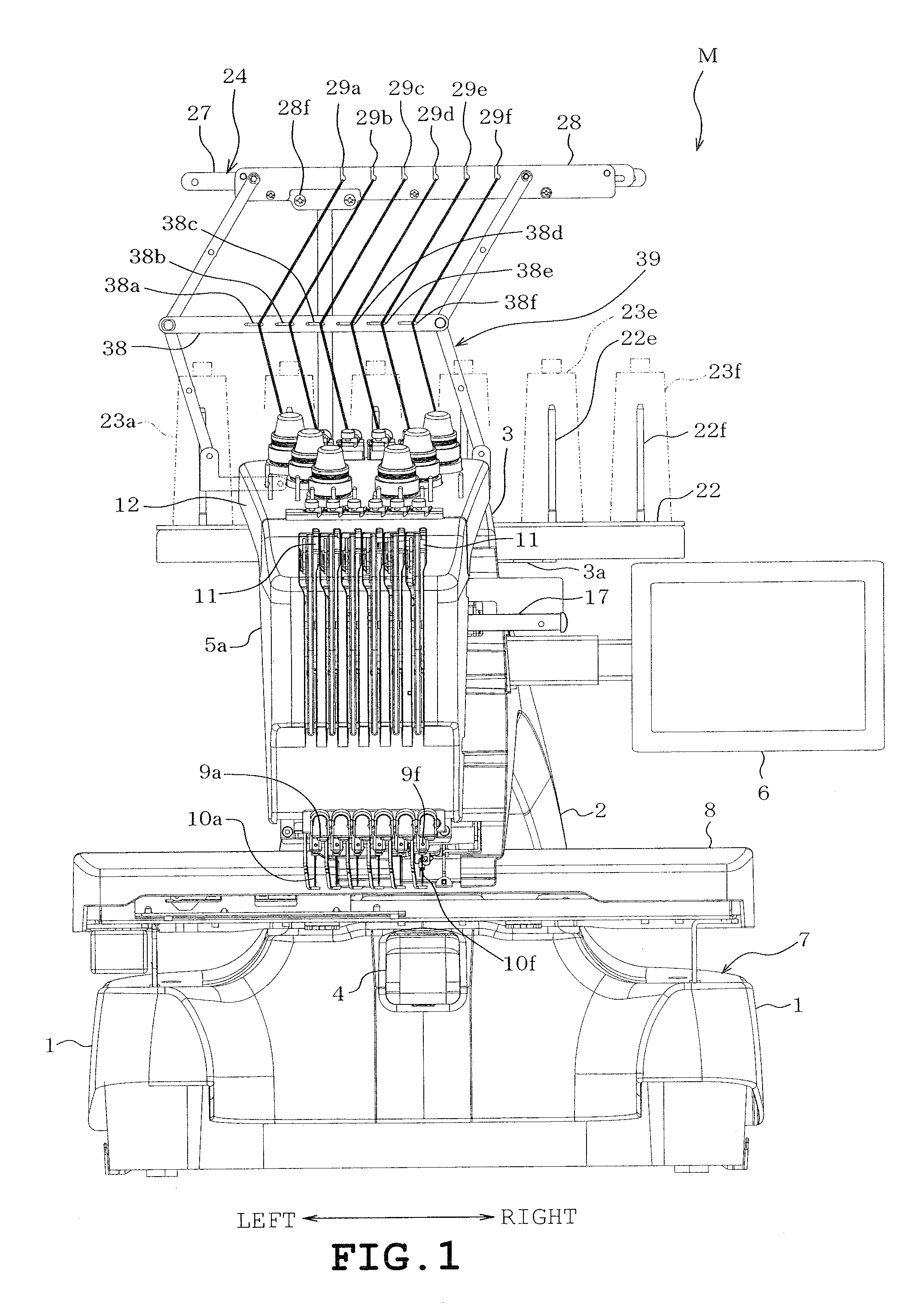
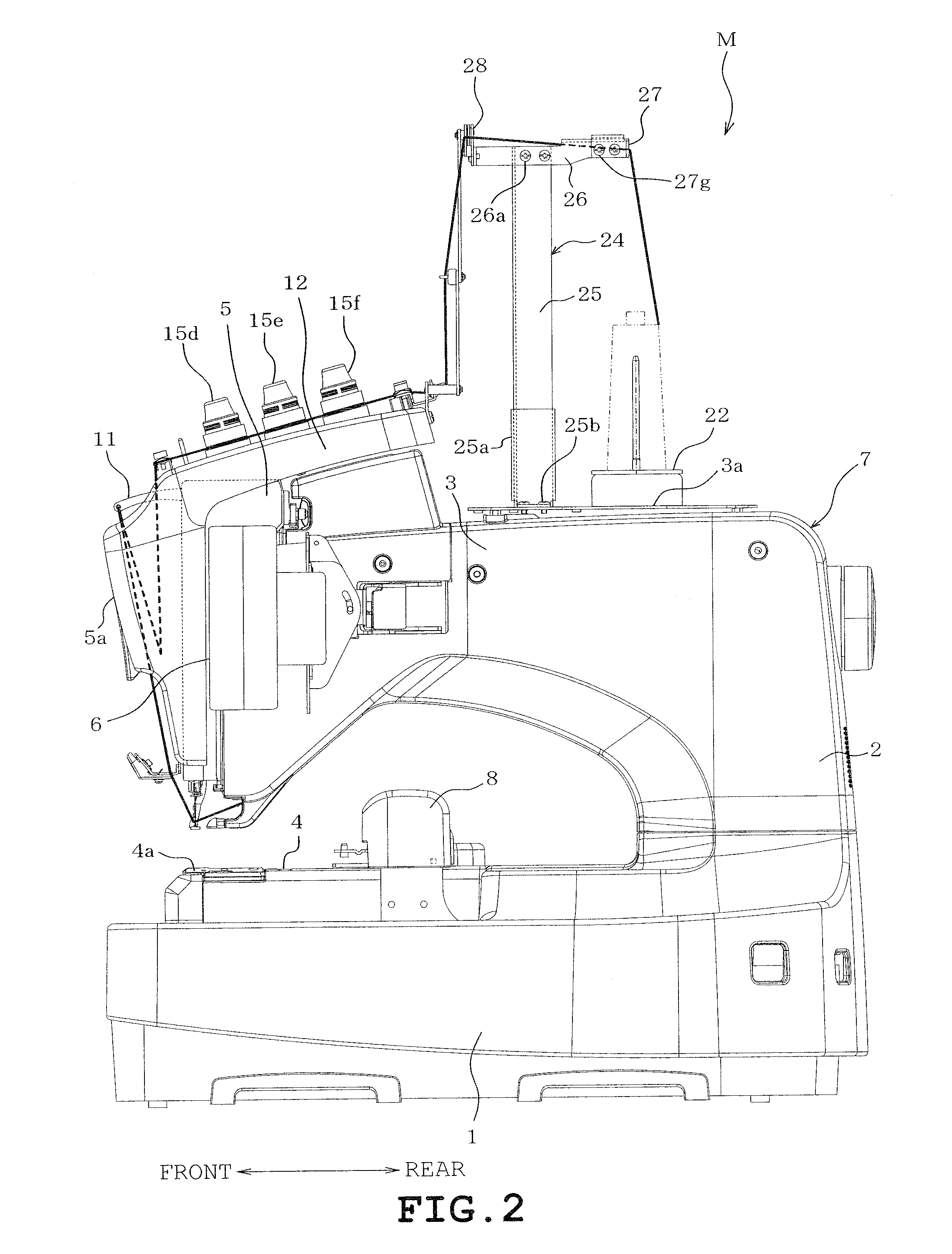
[0046]A first example will be described with reference to FIGS. 1 to 22. The side of a multi-needle sewing machine M where the user or operator is located is referred to as “front.”
[0047]Referring to FIGS. 1 to 5, the multi-needle sewing machine M includes a pair of right and left legs 1 supporting the overall sewing machine, a pillar 2 standing on rear ends of the legs 1, an arm 3 extending frontward from an upper part of the pillar 2, a cylinder bed 4 extending frontward from a rear end of the pillar 2, and a needle bar case 5 mounted on a front end of the arm 3. The legs 1, pillar 2, arm 3 and cylinder bed 4 are formed integrally with one another into a sewing machine body 7. A control device (not shown) controlling the overall multi-needle sewing machine M, an operation panel 6 and the like are provided at the sewing machine body 7 side. A needle plate 4a is mounted on an upper surface of the cylinder bed 4. The needle plate 4a is formed with a needle hole (not shown) serving as...
second example
[0073]FIG. 23 illustrates a second example. Two intermediate thread guide members 51 and 52 are added to the intermediate thread guide portion moving mechanism 39 in the second example. The upper intermediate thread guide member 51 is pivotally mounted between the intermediate portions of the first link members 40 and 41. The lower intermediate thread guide member 52 is pivotally mounted between the intermediate portions of the second link members 42 and 43. The intermediate thread guide members 51 and 52 are provided with the intermediate thread guide portions 51a-51f and 52a-52f guiding the threads Ia-If respectively in the same manner as the intermediate thread guide member 38. Although only one thread Ib is shown in FIG. 23 for the sake of easiness in the explanation of the operation of the intermediate thread guide portion moving mechanism, it is assumed that six threads Ia-If would be provided as shown in FIGS. 1 and 6.
[0074]According to the above-described second example, the...
third example
[0075]FIGS. 24 to 28 illustrate a third example. The third example differs from the first example in the construction of the intermediate thread guide portion moving mechanisms 61a to 61f. The intermediate thread guide portion moving mechanisms 61a to 61f are provided so as to correspond to the intermediate thread guide portions 62a to 62f (shown in FIG. 27) respectively. The intermediate thread guide portion moving mechanisms 61a to 61f have respective first arm members 63a to 63f and respective second arm members 64a to 64f. Pins 67a to 67f (see FIG. 26) are mounted on the machine frame side thread guide members 50 as to be located near the machine frame side 66a to 66f (substantially beneath the guide portions 66a-66f as viewed in FIG. 24) respectively. The first arm members 63a-63f have one ends which are pivotally mounted on the pins 67a to 67f respectively. Pins 68a to 68f (shown in FIG. 27) are mounted on one ends of the second arm members 64a-64f respectively. The first arm ...
PUM
 Abstract
Description
Claims
Application Information
 - R&D Engineer
- R&D Manager
- IP Professional
- Industry Leading Data Capabilities
- Powerful AI technology
- Patent DNA Extraction
Browse by: Latest US Patents, China's latest patents, Technical Efficacy Thesaurus, Application Domain, Technology Topic.
© 2024 PatSnap. All rights reserved.Legal|Privacy policy|Modern Slavery Act Transparency Statement|Sitemap