Method of and Apparatus for Cleaning a Floor

Active Publication Date: 2010-09-30
SCOT YOUNG RES LTD
View PDF8 Cites 3 Cited by
  • Summary
  • Abstract
  • Description
  • Claims
  • Application Information

AI Technical Summary

Benefits of technology

[0008]The method of the present invention enables a cleaning operative to clean a floor leaving it substantially dry, rather than in a wet state as with known methods, thus reducing the risk of a person slipping on the floor, and minimising the use of “wet floor” warning signs which commonly are used and themselves provide hazards.
[0009]This is achieved because the jaws of the wringer act on and thus wring substantially all of the absorbent fabric material so that the fabric material is only just damp when the floor is cleaned. No pools of liquid are thus left by the mop (or by a squeegee which is sometimes used to move residual liquid over the floor in an effort to promote faster floor drying), and accordingly the floor may efficiently be dried by the separate drying tool. If the floor after mopping was too wet, the dry cloth of the drying tool would too readily become wet and rapidly require replacement or drying.
[0010]According to the method of the invention, the wringer thus may be designed to co-operate with a specific kind and size of flat mop head rather being of a more-general design. Any disadvantage this may present in terms of the versatility of use of the wringer, is offset by the advantage of being able to clean a floor and leave it substantially dry.
[0013]In the present invention, the wringer may be designed so that the jaws are moveable together by operation of a wringer mechanism, to a closed condition in which the distance between the jaws, or at least the widest distance between them, is reduced compared with previous proposals, for example so that their distance or widest distance apart when fully closed together, is not significantly greater than the folded thickness of the foldable parts of the mop head including any space between them, and preferably is less than the folded thickness, so that the jaws may act upon substantially all of the absorbent fabric material to wring the fabric material between the jaws and the wringing surface of the wringer.
[0016]The method may include yet further adjusting the position of the operating edge relative to the cloth, and performing further drying by moving the head over the floor and urging the head towards the floor with a third region of the cloth between the operating edge and the floor.
[0028]Typically, no part of the mop head will be introduced between the jaws during wringing, but only the loop of absorbent material so that a gap with shape and area less than the cross sectional area of the folded parts may be provided when the jaws are fully closed, to facilitate substantially all of the absorbent material being wrung out.

Problems solved by technology

If the floor after mopping was too wet, the dry cloth of the drying tool would too readily become wet and rapidly require replacement or drying.

Method used


Image

  • Method of and Apparatus for Cleaning a Floor
  • Method of and Apparatus for Cleaning a Floor
  • Method of and Apparatus for Cleaning a Floor

Examples


Embodiment Construction

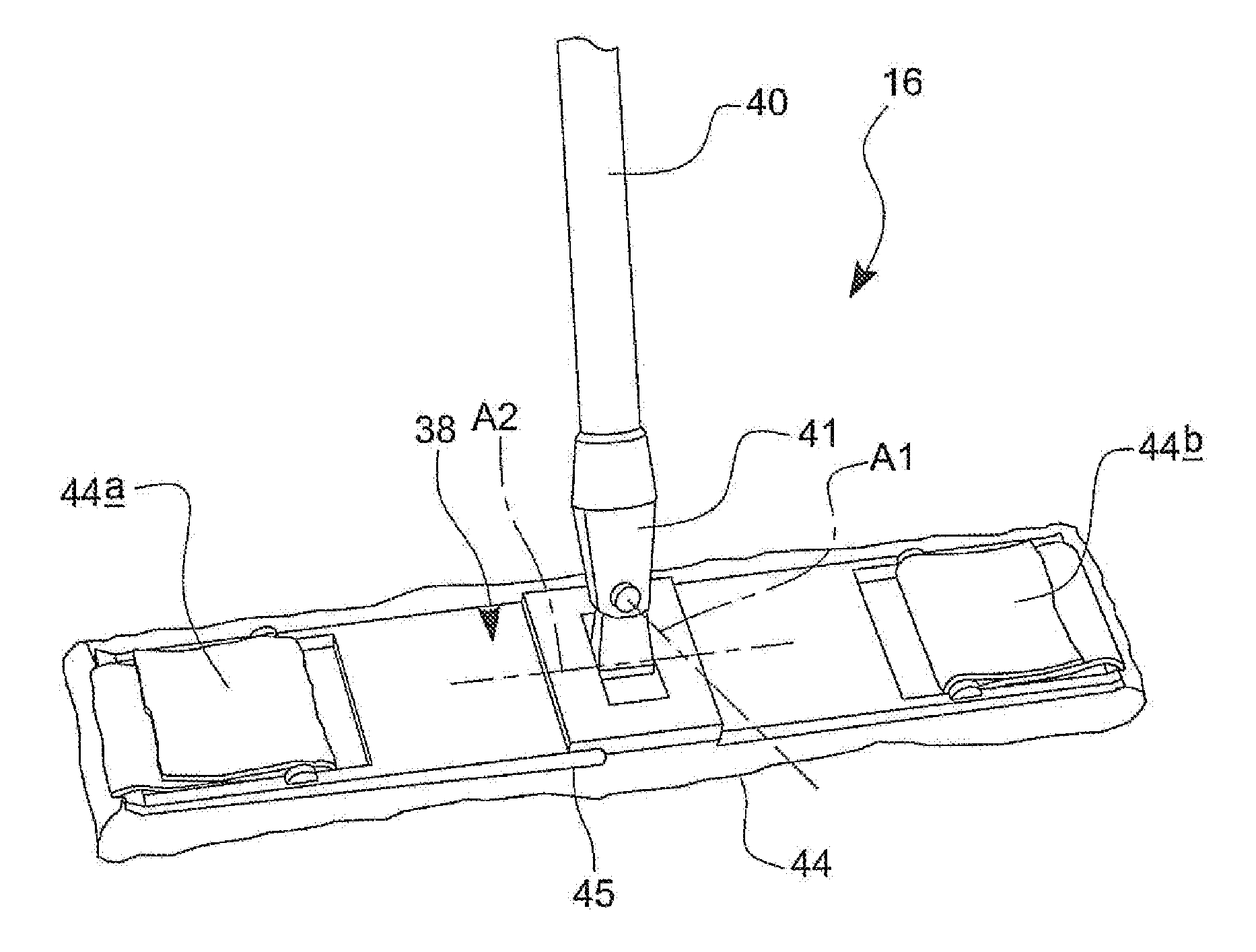
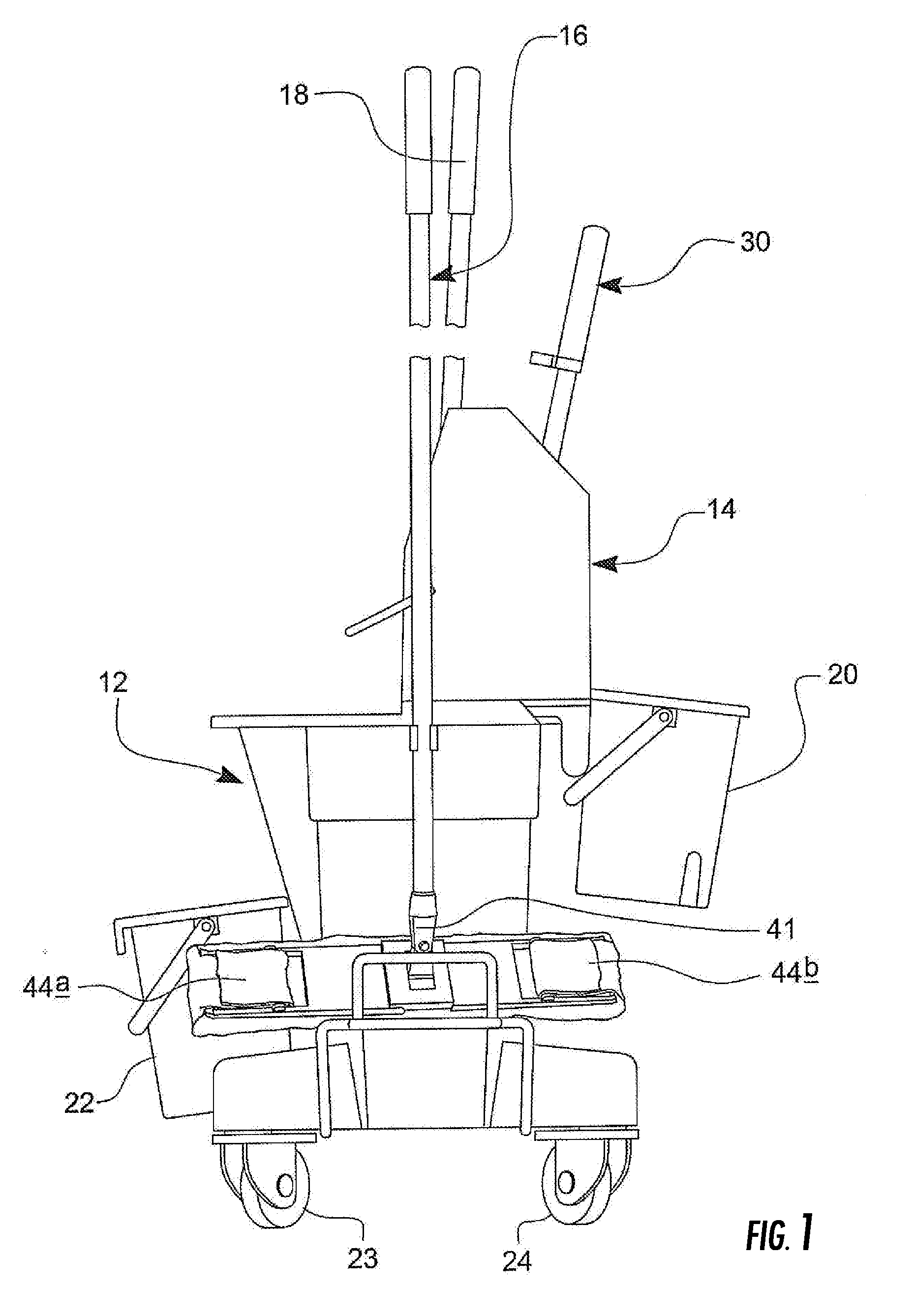
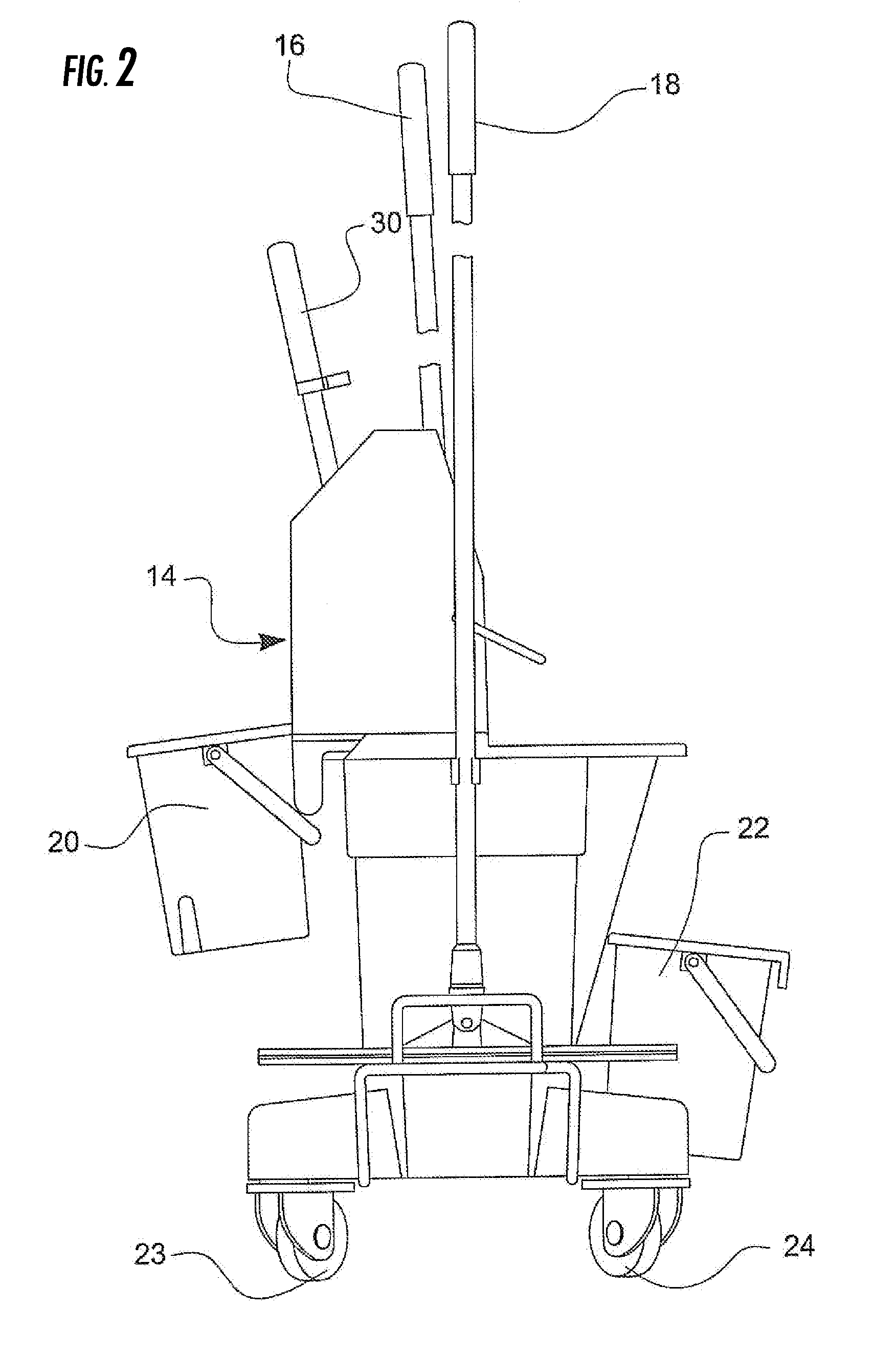
[0051]Referring to FIG. 1 an apparatus 10 for cleaning a floor is shown, which apparatus 10 is generally self contained, and includes a container12 for containing a floor cleaning liquid, a wringer 14 carried by the container 12, a flat mop 16, and a drying tool 18. The apparatus 10 further includes a receptacle 20 for a store of floor drying cloths, and a receptacle 22 for used, wet, floor drying cloths.

[0052]The container 12 is typically provided by a plastic moulding, to which two pairs of wheels 23, 24 may be mounted, or the container 12 may be assembled to a separate wheeled dolly, or the container 12 may otherwise be carried on wheels 23, 24 which enable the container 12 to be wheeled to a floor to be cleaned, typically with floor cleaning liquid contained in the container.

[0053]The wringer 14 is integral with the container 12, or is mounted on an upper rim of the container 12, and / or is partially mounted in the container and / or over the rim. In each case the wringer 14 is car...


PUM

PropertyMeasurementUnit
Thicknessaaaaaaaaaa
Electrical resistanceaaaaaaaaaa
Areaaaaaaaaaaa

Abstract

A method of cleaning a floor uses a flat mop including a generally flat mop head having a handle and absorbent fabric material. The mop head is foldable to a folded condition, wherein a loop of the fabric material depends from the folded parts. The fabric material is inserted into cleaning liquid to wet the material. The mop head is introduced to a wringer to wring the material between the jaws and a wringing surface. The damp absorbent fabric material is used to mop the floor. The floor is dried using a separate drying tool that includes a head secured to a handle, and one or more attachment devices to attach a dry absorbent cloth to the head. The floor is dried by applying the cloth to the floor using the tool and moving a dry portion of the cloth over the floor.

Description

CROSS-REFERENCE TO RELATED APPLICATIONS[0001]This application claims priority from U.K. Patent Application No. GB 905953.5, filed Mar. 25, 2009.BACKGROUND OF THE INVENTION[0002]This invention relates to a method of cleaning a floor and to an apparatus for cleaning a floor.[0003]There are several different kinds of mops, one of the most widely used including a mop head to which a handle is secured, the mop head carrying a plurality of absorbent filaments e.g. of string, which depend from the mop head. The filaments are in use, wetted with a cleaning liquid, wrung out with a wringer, and then the mop is used to clean the floor, whilst still in a wet condition.[0004]Although mechanically assisted wringers which include mechanically moveable jaws which press down on the filaments can wring out most of the cleaning liquid, such mops when wrung out, are still wetter than is ideally required, and a cleaned floor thus remains wet after cleaning, for typically at least several minutes, which...

Claims


Application Information

Patent Timeline
IPC IPC(8): B08B7/00A47L13/20
CPCA47L13/253A47L13/59A47L13/258A47L13/10A47L13/16A47L13/58
Inventor YOUNG RONALD ALEXANDER (SCOT)
Owner SCOT YOUNG RES LTD
Why Eureka
Try Eureka