
Flat Roof Mounted Solar Panel Support System

a solar panel and support system technology, applied in the direction of solar heat collector mounting/support, solar heat collector safety, light and heating equipment, etc., can solve the problems of emergency personnel, need to occur, and the like, and achieve the effect of convenient installation of solar power systems

Inactive Publication Date: 2010-09-30
SOLARPOWER
View PDF69 Cites 125 Cited by
  • Summary
  • Abstract
  • Description
  • Claims
  • Application Information

AI Technical Summary

Benefits of technology

"The present invention is a solar power system that can be adapted to different needs and roof conditions. It includes various embodiments that can be combined in different ways to create different solutions. The design includes quick fasteners and emergency releases to aid in installation and potential emergency situations. The system also includes special components that maintain the integrity of the roof and enhance the overall appearance of the solar power system. The design is flexible and can adjust to roof irregularities. The technical effects of the invention include efficient and flexible installation, improved safety, and enhanced aesthetics."

Problems solved by technology

This can need to occur under adverse conditions such as smoke, fire, rain, wind, or at nighttime.
Removing solar panels or the like can be particularly challenging when the solar power systems are designed to produce electrical power.
This can be challenging for emergency personnel as it is undesirable for them during firefighting or other operations to be exposed to live electrical wires.
In addition, the initial cost of the system should not be increased significantly for simply the action of installing it on a pre-existing roof or other surface.
Furthermore, the cost of the solar panels and other such componentry itself is significant enough that the cost of an underlying structure, should not be so large as to greatly increase the cost of the overall system.
The more time an installer needs to spend on a roof or other area installing individual componentry, the more expensive the overall system is to a user.

Method used


Image

  • Flat Roof Mounted Solar Panel Support System
  • Flat Roof Mounted Solar Panel Support System
  • Flat Roof Mounted Solar Panel Support System

Examples


Embodiment Construction

[0039]As mentioned earlier, the present invention includes a variety of aspects, which may be combined in different ways. The following descriptions are provided to list elements and describe some of the embodiments of the present invention. These elements are listed with initial embodiments, however it should be understood that they may be combined in any manner and in any number to create additional embodiments. The variously described examples and preferred embodiments should not be construed to limit the present invention to only the explicitly described systems, techniques, and applications. Further, this description should be understood to support and encompass descriptions and claims of all the various embodiments, systems, techniques, methods, devices, and applications with any number of the disclosed elements, with each element alone, and also with any and all various permutations and combinations of all elements in this or any subsequent application.

[0040]As can be seen fr...


PUM

PropertyMeasurementUnit
solar poweraaaaaaaaaa
poweraaaaaaaaaa
areaaaaaaaaaaa

Abstract

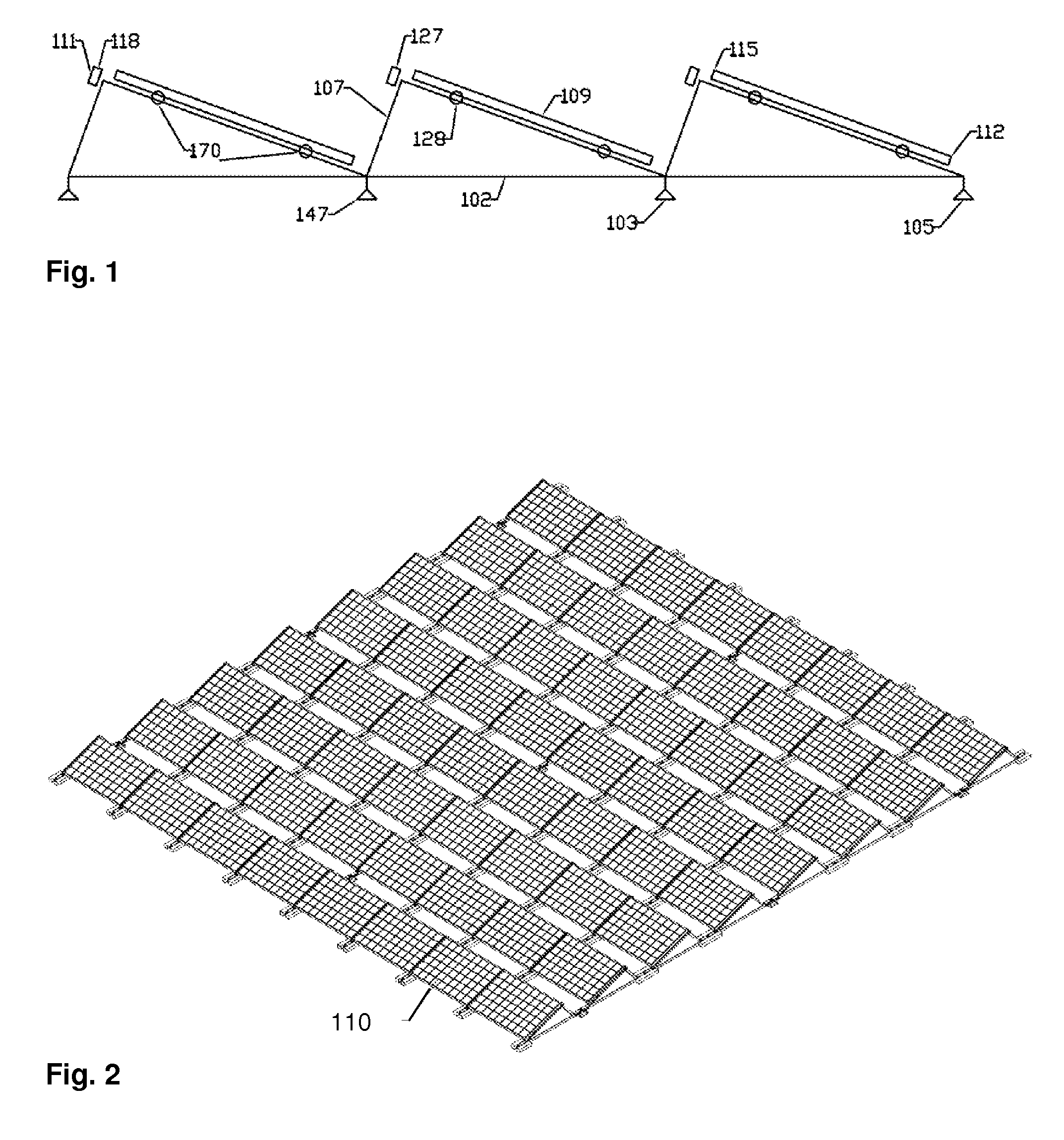
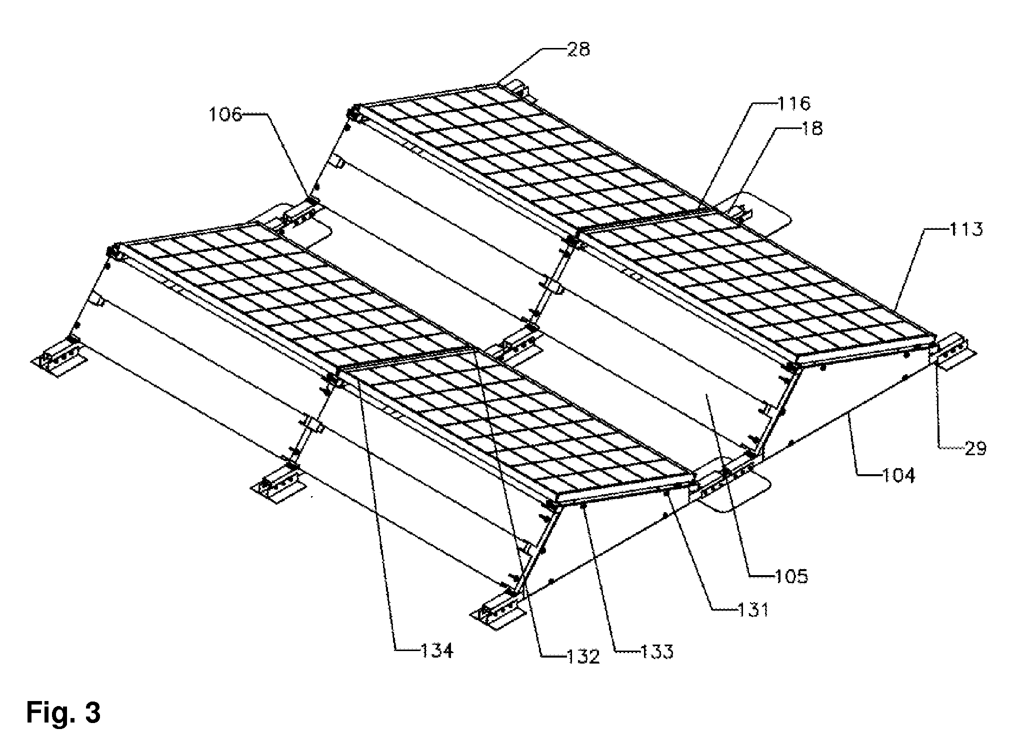
A solar power system is mounted to a solar power componentry support structure (104) suspended above a pre-existing surface (101) by a collective of solar collector suspension base supports (103) Suspended solar power system row support structure members (105) and suspended solar power system column support structure members (106) may for a solar component position lattice (107) to which a matrix of individual solar power components such as solar panels (18) can be attached Solar module quick-fasten assemblages (111) may serve also as solar componentry emergency releases (118) and may include loose axis retainers (128) and firm axis fasteners (127) such as dual component, single point operative emergency releases (121) and fasteners Slide-in retainers and corner slot tabs (136) can be included as well as frame alignment notches (138) Fulcrum pivot fasteners (139) and slide wedge releases (142) can aid in installation and release

Description

TECHNICAL FIELD[0001]This invention relates to the field of solar panel support systems such as for flat or low pitch roofs that are very easy to install, low cost, and incorporate a number of safety systems. Solar collector PV module arrays are formed by a plurality of solar panels on a support system which can be either laid on a roof with no penetration, with ballast and no penetrations or penetrations, or any combination of the three types.BACKGROUND[0002]The field of solar power has become very important. Solar power systems can be installed in huge seas as well as for individual residential and commercial usage. These individual systems can supply power to an underlying structure, and can also supply excess power into the grid or the like. For individual systems, it is not uncommon to locate these systems on the roofs of buildings. These roofs can be angled roofs or flat roofs. In many commercial applications a flat roof is frequently encountered and the solar panel system is ...

Claims


Application Information

Patent Timeline
Patent Type & Authority Applications(United States)
IPC IPC(8): H01L31/042B23P11/00
CPCF24J2/4607Y10T29/49002F24J2/5233F24J2/5239F24J2/5245F24J2/5254F24J2/5264F24J2002/5294Y02B10/12Y02B10/20Y02E10/47Y02E10/50F24J2002/5292H02S20/00H02S20/24F24J2002/4661Y10T29/49826F24J2/4638F24S25/13F24S25/16F24S25/61F24S25/632F24S25/70F24S40/00F24S40/85F24S2025/02F24S2025/021F24S2025/6002Y02B10/10H02S30/10
Inventor PATTON, JOHN C.LI, YANGLINZHANG, ZHENGXUE
Owner SOLARPOWER
Learn More