Disk brake for vehicle

a technology for brakes and disks, applied in the direction of brake types, slack adjusters, brake elements, etc., can solve problems such as cronk noise, and achieve the effect of preventing cronk noise and simple structur

Active Publication Date: 2010-09-30
HITACHI ASTEMO LTD
View PDF8 Cites 20 Cited by
  • Summary
  • Abstract
  • Description
  • Claims
  • Application Information

AI Technical Summary

Benefits of technology

[0012]According to the disk brake for a vehicle of the present invention, since the lug pieces of the friction pad are urged outside in the radial direction of the disk by the pad resilient parts of the pad retainer, even when the vibration occurs during an ordinary driving, the friction pad is held at a prescribed position in a stable condition. Further, even when the vibration larger than an ordinary vibration is applied to a vehicle body, for instance, when the vehicle gets over a stepped part during the driving, the friction pad temporarily moves inside in the radial direction of the disk against the urging force of the pad resilient parts, then, is urged outside in the radial direction of the disk by the urging force of the pad resilient parts and the lug pieces are apt to collide with the outer side surfaces of the pad guide grooves in the radial direction of the disk through the outer side pieces of the pad retainer, since the outer side pieces are provided with the impact suppressing parts for suppressing the collision of the lug pieces with the outer side surfaces in the radial direction of the disk through the outer side pieces, the force of the lug pieces in the direction of collision is absorbed by the impact suppressing parts and the generation of cronk noise can be prevented.
[0013]Further, when the impact suppressing parts are formed by stepped parts which are formed by bending the outer side pieces, the impact suppressing parts can be formed by a simple method that the outer side pieces are merely bent, and the force of the lug pieces in the direction of collision can be effectively absorbed by spaces formed between the outer side pieces and the outer side surfaces of the pad guide grooves in the radial direction of the disk.
[0014]Further, in the outer sides of the pad guide grooves of the caliper support arms in the radial direction of the disk, the pad retainer attaching parts are provided that have the attaching surfaces parallel to the outer side surfaces in the radial direction of the disk. The pad retainer is attached to the caliper support arms in such a way that the end parts of the groove opening side parts of the outer side pieces are bent back along the attaching surfaces of the pad retainer attaching parts to form the attaching pieces and the pad retainer attaching parts are sandwiched between the attaching pieces and the outer side pieces to

Problems solved by technology

However, when the vibration larger than an ordinary vibration is applied to a vehicle body, for instance, when the vehicle gets over a stepped part during the driving, occasionally, the friction pad temporarily moves inside in the radial direction of the disk against the urging force of the pad retain

Method used


Image

  • Disk brake for vehicle
  • Disk brake for vehicle
  • Disk brake for vehicle

Examples


Embodiment Construction

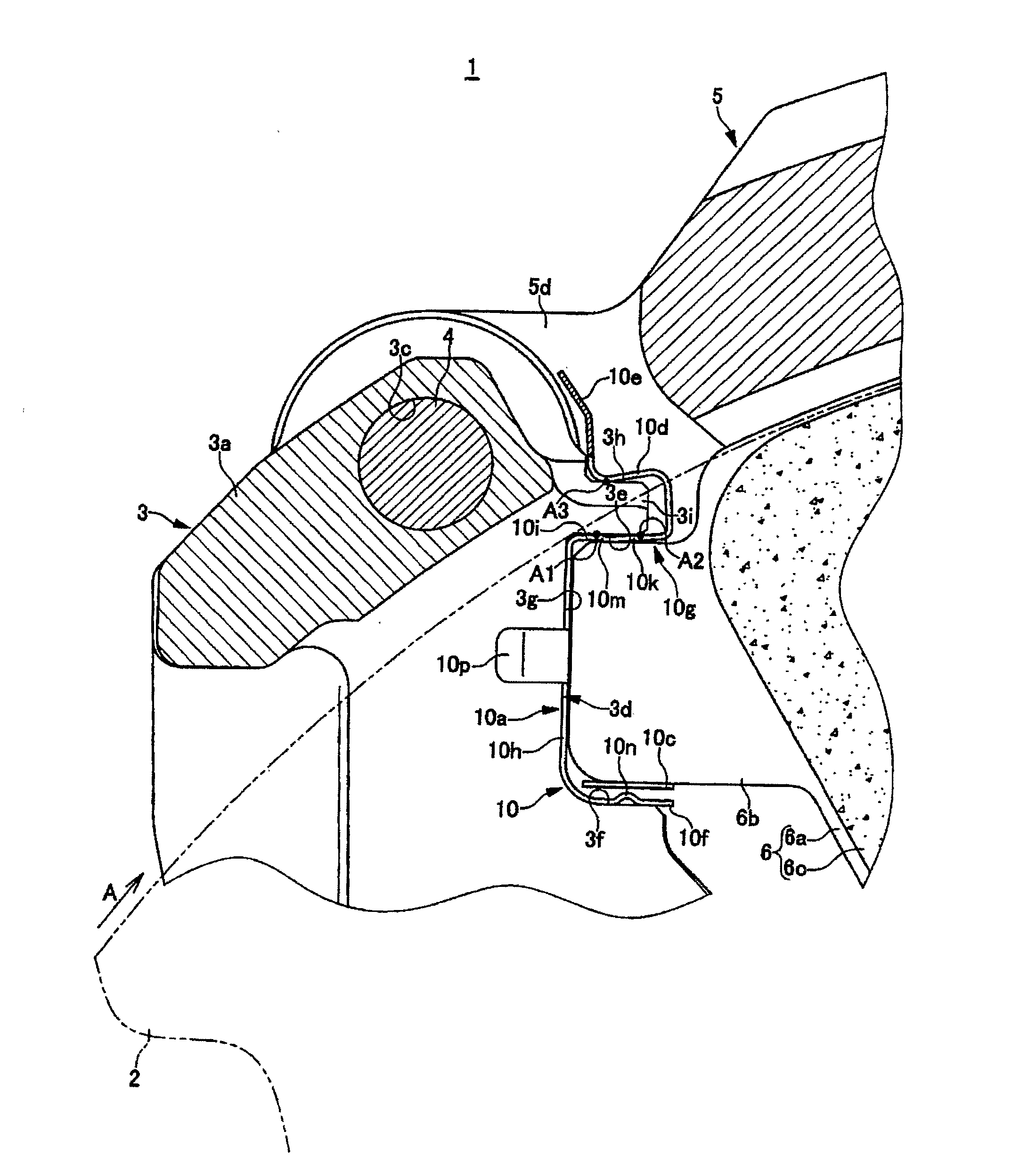
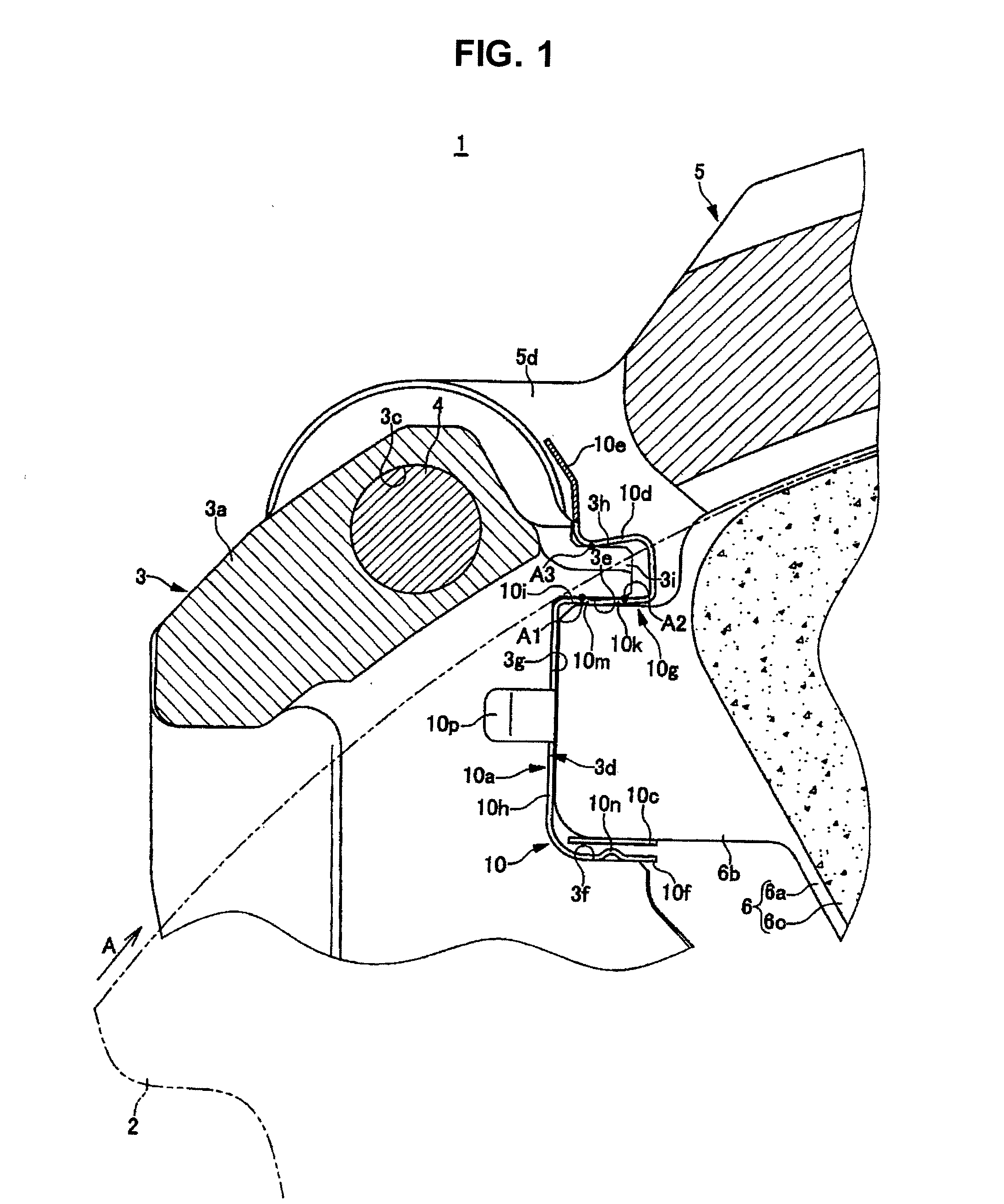
[0028]FIGS. 1 to 7 are diagrams showing a first exemplary embodiment of a disk brake for a vehicle of the present invention. An arrow mark A designates a rotating direction of a disk rotor that rotates integrally with a front wheel when a vehicle moves forward. A disk come-out side and a disk come-in side which are described below indicate sides when the vehicle moves forward.

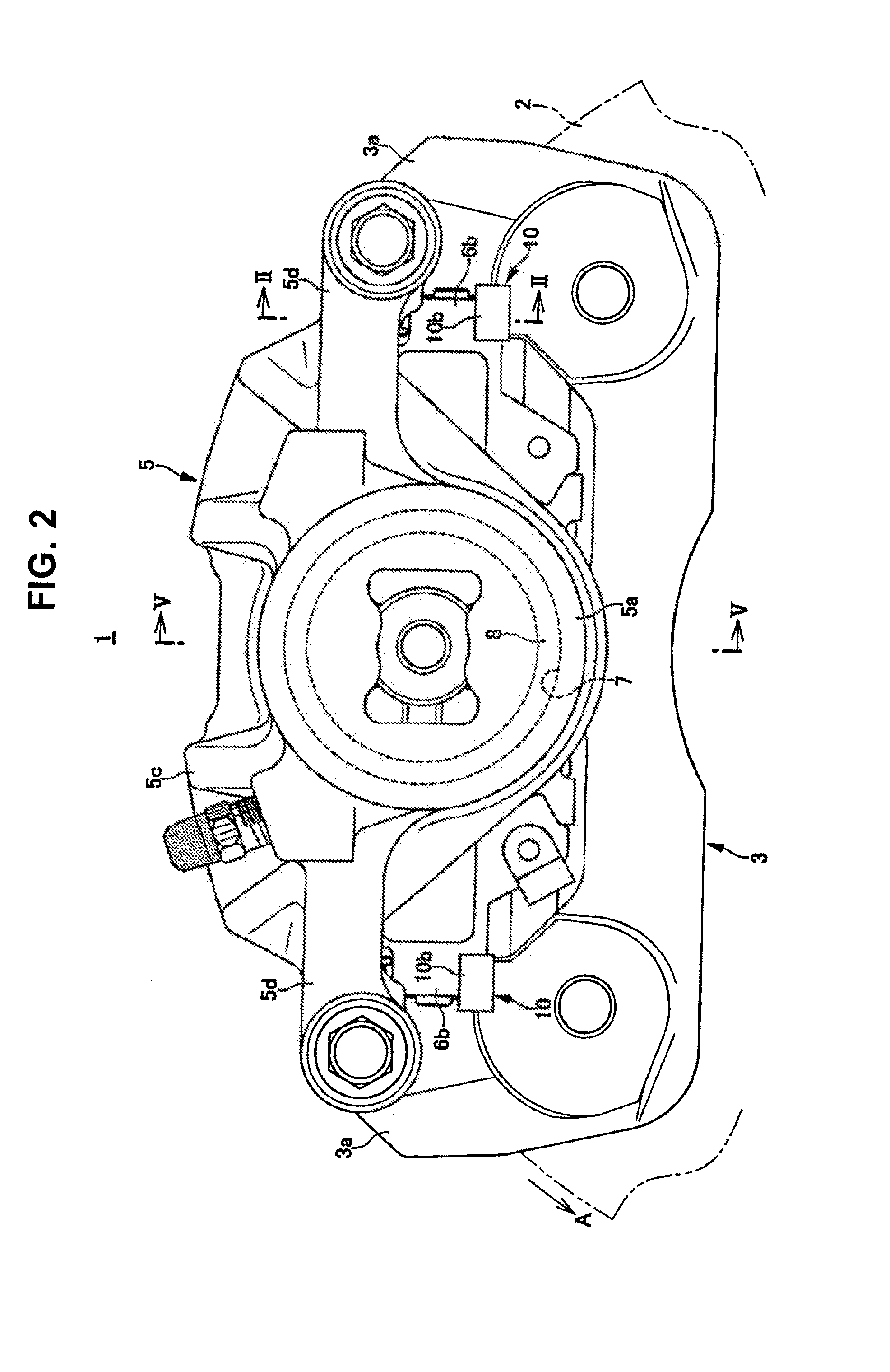
[0029]The disk brake 1 for the vehicle includes a disk rotor 2 rotating integrally with a wheel, a caliper bracket 3 fixed to a vehicle body at one side part of the disk rotor 2, a calipers body 5 supported on caliper support arms 3a and 3a so as to be movable in the axial direction of a disk through a pair of slide pins 4 and 4 and a pair of friction pads 6 and 6 opposed to each other with the disk rotor 2 sandwiched between them inside an action part 5a and a reaction part 5b of the caliper body 5.

[0030]The caliper body 5 includes the above-described action part 5a and the reaction part 5b arranged at both th...


PUM


Abstract

A disk brake for a vehicle includes: a caliper bracket; a pair of caliper support arms; pad guide grooves that have outer side surfaces, inner side surfaces and opposed surfaces; and lug pieces that protrude on both side parts of back plates of friction pads supported by the pad guide grooves through a pad retainer, the pad retainer including a pair of retainer parts, a connecting piece and pad resilient parts, wherein: the retainer parts include inner side pieces arranged along the inner side surfaces of the pad guide grooves, outer side pieces arranged along the outer side surfaces of the pad guide grooves and interior pieces that connect the outer side pieces to the inner side pieces; and the outer side pieces include impact suppressing parts that restrain the lug pieces from colliding with the outer side surfaces through the outer side pieces.

Description

BACKGROUND[0001]1. Field of the Invention[0002]The present invention relates to a disk brake for a vehicle used in a motor vehicle or a motor bicycle, and more particularly to a structure of a pad retainer that supports lug pieces of a back plate of a friction pad by pad guide grooves of caliper support arms.[0003]2. Description of the Related Art[0004]In a disk brake in which lug pieces respectively protruding at both side parts of a back plate of a friction pad are supported by pad guide grooves formed and opposed to each other in a pair of caliper support arms so as to move the friction pad in the axial direction of a disk, a pad retailer formed with a metal thin plate is ordinarily interposed between the pad guide grooves and the lug pieces. In such a pad retainer, a pad retainer is known that includes resilient parts abutting on the lug pieces to urge the lug pieces toward sides opposite to a disk rotor and urge the lug pieces toward outer side surfaces of the pad guide grooves...

Claims


Application Information

Patent Timeline
IPC IPC(8): F16D65/097F16D65/40
CPCF16D65/0977F16D65/0972
Inventor MIURA, YASUTAKAASAHI, KENJIHANAKI, YOSHIHIKO
Owner HITACHI ASTEMO LTD
Why Eureka
Try Eureka