Displaceable utility positioning system for motorcycles

a utility positioning and motorcycle technology, applied in the direction of article supporting devices, cycle equipment, manufacturing tools, etc., can solve the problems of reducing the service life of the rider,

Inactive Publication Date: 2010-09-30
STP IND
View PDF62 Cites 39 Cited by
  • Summary
  • Abstract
  • Description
  • Claims
  • Application Information

AI Technical Summary

Benefits of technology

[0008]In accordance with yet another representative embodiment described herein, a method is provided for selectively displacing a utility component about a rear fender of a motorcycle. The method includes operating a positioning system mounted about the rear fender that is operable to locate the utility in one of a plurality of positions. The positioning system comprises a mounting assembly having first and second side mounts securable about opposing sides of the rear fender, a carriage slidably coupled to the mounting assembly and configured to support the utility, a riser operable to elevate the carriage above the upper surface of the rear fender, and a locking device such that the carriage may be locked in a plurality of forward and rearward positions above the rear fender. The method further includes positioning the carriage and the utility in a rearward position to expose the upper surface of the fender, and attaching a separate, supplemental passenger seat configured to removably interface with the upper surface of the rear fender when the carriage and utility are located in the rearward position. Once in the rearward position, a passenger may further adjust the carriage and the utility to provide the desired posterior support that is most comfortable to the passenger.

Problems solved by technology

Making the transition between a one-seat arrangement of the motorcycle and a two-seat configuration can be difficult and time-consuming.
Obviously, once the transition has been made to reposition the cargo box to accommodate a passenger, the posterior support is lost for the rider and is not easily recovered without a similar difficult transition to again locate the cargo box in a forward position.
Previous efforts to provide an adjustable cargo box that can move between the forward and rearward positions without having to remove the container from the motorcycle have been met with limited success, as any adjustable mounting system must be sufficiently robust to secure the cargo box in at least two positions and also guard against the high-vibration operating conditions encountered with motorcycles.
If left unaccounted for, the high level of vibration could lead to fatigue and eventual failure of the mechanical components, which could be disastrous for the rider and / or passenger of the motorcycle if the failure occurs while traveling on the open road.
In addition, such adjustable systems have also been limited in their range of travel back and forth over the rear fender of the motorcycle and their ability to accommodate riders and passengers of all sizes.

Method used


Image

  • Displaceable utility positioning system for motorcycles
  • Displaceable utility positioning system for motorcycles
  • Displaceable utility positioning system for motorcycles

Examples


embodiment 20

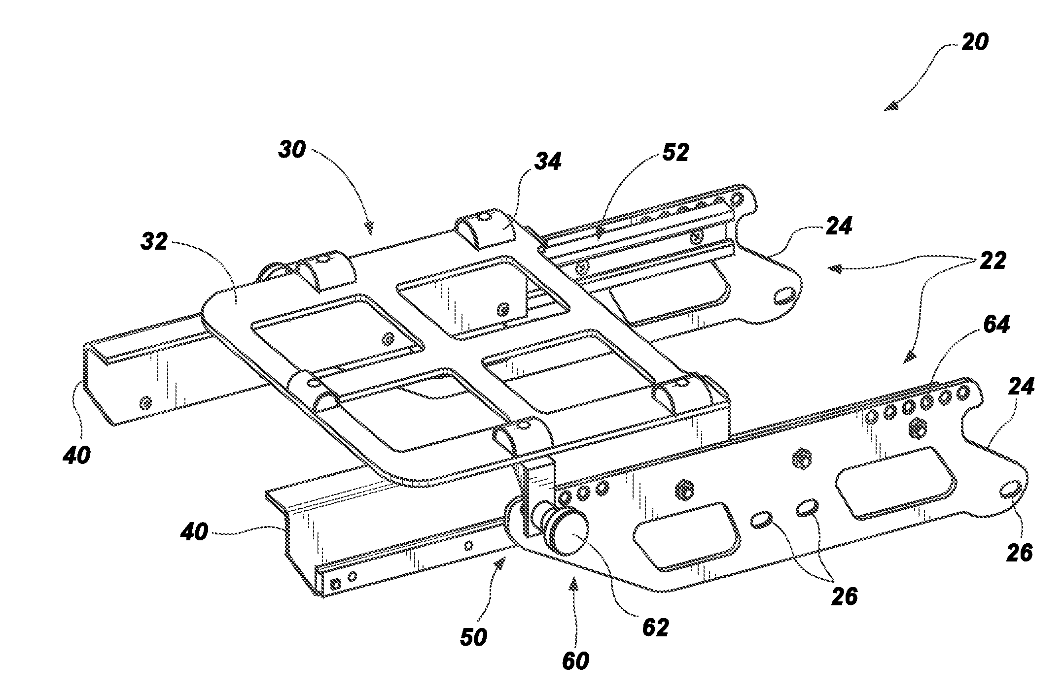
[0059]The positioning system 20 can further include a riser 40 that is operable to elevate the carriage 30 over the top of the rear fender, as the side mounts 24 can be attached low to the sides of the motorcycle utilizing the pre-existing mounting points. The riser 40 can be configured with sufficient height for the carriage to clear the rear fender while moving through its entire range of motion, to avoid contacting or damaging the fender, while still maintaining both the base of the storage utility and the removable passenger seat in as low a position as possible. As shown in the embodiment 20 of FIG. 4, the riser 40 can be part of the moveable sliding carriage 30. Alternatively, in another aspect the riser can be part of the stationary mounting assembly.

[0060]As further illustrated in FIG. 4, the moveable carriage 30 can be slidably coupled to the mounting assembly with a pair of sliding mechanisms 50, such as linear bearings 52. Other sliding mechanisms may comprise slide rails...

embodiment 100

[0081]To enhance the interconnection, the second carriage portion can be further secured to the first carriage portion with the inner coupling devices 160, which devices operate to lock the first and second carriage portions together with a six-point interconnection. As shown in FIG. 11, the inner coupling devices 160 of the second carriage portion 140 can be coupled to the sliding mechanism 122 at the coupling stub 136, which may also be located rearward of the rear attachment journals 128 in the embodiment 100 to provide a longer stance or base that better stabilizes and secures the carriage assembly.

[0082]The sliding mechanism 122 of the first carriage portion 120 is shown with more detail in FIG. 12, and can provide the positioning system with a stiffness and rigidity sufficient to allow the front half of the carriage assembly to be substantially cantilevered at, near or even beyond the forward edges of the side mounts 114 in the forward position, and the back half of the carria...

embodiment 102

[0088]FIGS. 15-17 also serve to illustrate another embodiment 102 of the displaceable positioning system and seating system that includes a different type or configuration of a utility 178 which can be used to attach a shell (not shown) of a different type (e.g., a shell having smaller dimensions) above the rear fender 194 of the motorcycle 190. The smaller utility 178 can be attached to or integrated with the second carriage portion 140 so that the riser brackets 142 are connected together with cross bars 146 to form a frame 179 having bolt holes 148 formed into the forward cross-bar which can be used attach the shell to the utility 178. The riser bracket comprises rear attachment notches 152 and front attachment notches 150.

[0089]Like the previously-described embodiment, the utility 178 / second carriage portion 140 can be coupled to the first carriage portion 120 by first moving the sliding mechanism 122 of the first carriage portion to a most forward position against a forward sto...


PUM

PropertyMeasurementUnit
lengthaaaaaaaaaa
timeaaaaaaaaaa
sizesaaaaaaaaaa

Abstract

A positioning system operable about a motorcycle for selectively locating a utility, such as a storage utility or a back rest utility, in one of a plurality of positions about a rear fender of the motorcycle. The positioning system includes a mounting assembly having first and second side mounts securable about opposing sides of the rear fender. The positioning system also includes a carriage configured to support the utility, and which is slidably coupled to the mounting assembly, and which has a range of travel defined by a centerline of the carriage that translating at least the entire length of the side mounts between a most forward position and a most rearward position. The positioning system further includes a riser operable to elevate the carriage above an upper surface of the rear fender, and a locking device that allows the carriage to be locked in a plurality of positions above the rear fender of the motorcycle.

Description

RELATED APPLICATIONS[0001]This application claims the benefit of U.S. Provisional Application No. 61 / 163,418, filed Mar. 25, 2009, and U.S. Provisional Application No. 61 / 312,115, filed Mar. 9, 2010, each of which is incorporated by reference in its entirety herein.FIELD OF THE INVENTION[0002]The present invention relates generally to back support systems for riders of motorcycles, and more specifically to displaceable and optionally removable and interchangeable back support systems for riders of motorcycles.BACKGROUND OF THE INVENTION AND RELATED ART[0003]Motorcycles are often sold with storage containers or cargo boxes attached to the motorcycle and located behind a single rider, and which are securely mounted with fixed brackets that prevent the often-weighty container from falling off or shifting as the motorcycle is maneuvering along the roadway. If it becomes desirable to add a supplemental passenger seat behind the rider's seat, the cargo box must be completely removed and a...

Claims


Application Information

Patent Timeline
Patent Type & Authority Applications(United States)
IPC IPC(8): B62J9/00B23P17/04B60R11/00B62J9/40
CPCB62J1/12B62J7/04Y10T29/49826F16C29/045B62J9/001B62J9/23B62J9/27
Inventor SALISBURY, RICK
Owner STP IND
Why Eureka
Try Eureka