Heated optical components

Inactive Publication Date: 2010-09-30
DH TECH DEVMENT PTE
View PDF5 Cites 3 Cited by
  • Summary
  • Abstract
  • Description
  • Claims
  • Application Information

AI Technical Summary

Benefits of technology

[0011]Further, in accordance with various embodiments of applicant's teachings an optical component assembly for use with a laser in laser desorption ionization is provided. The assembly includes a support, an optical c

Problems solved by technology

With known MALDI sources, however, the laser light hits the sample and forms a plume of debris, or vaporized mixture of sample, matrix material and sample ions.
Since some of the optical components, such as, for example, but not limited to, the laser mirror, lie in the path of the expanding plume, the surface of these components can become contaminated.
The cleaning of the mirror can be inconvenient a

Method used


Image

  • Heated optical components
  • Heated optical components
  • Heated optical components

Examples


Embodiment Construction

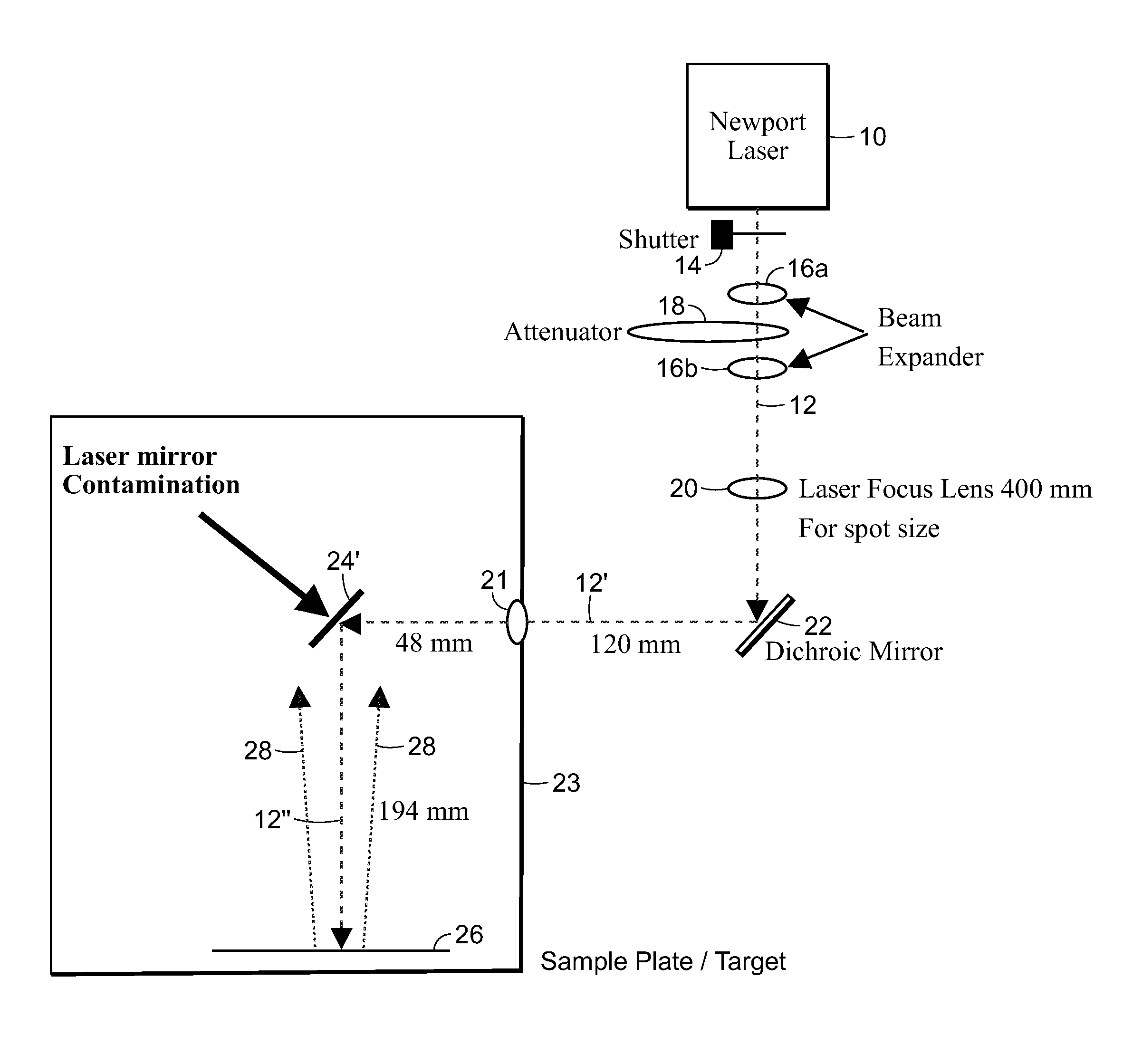
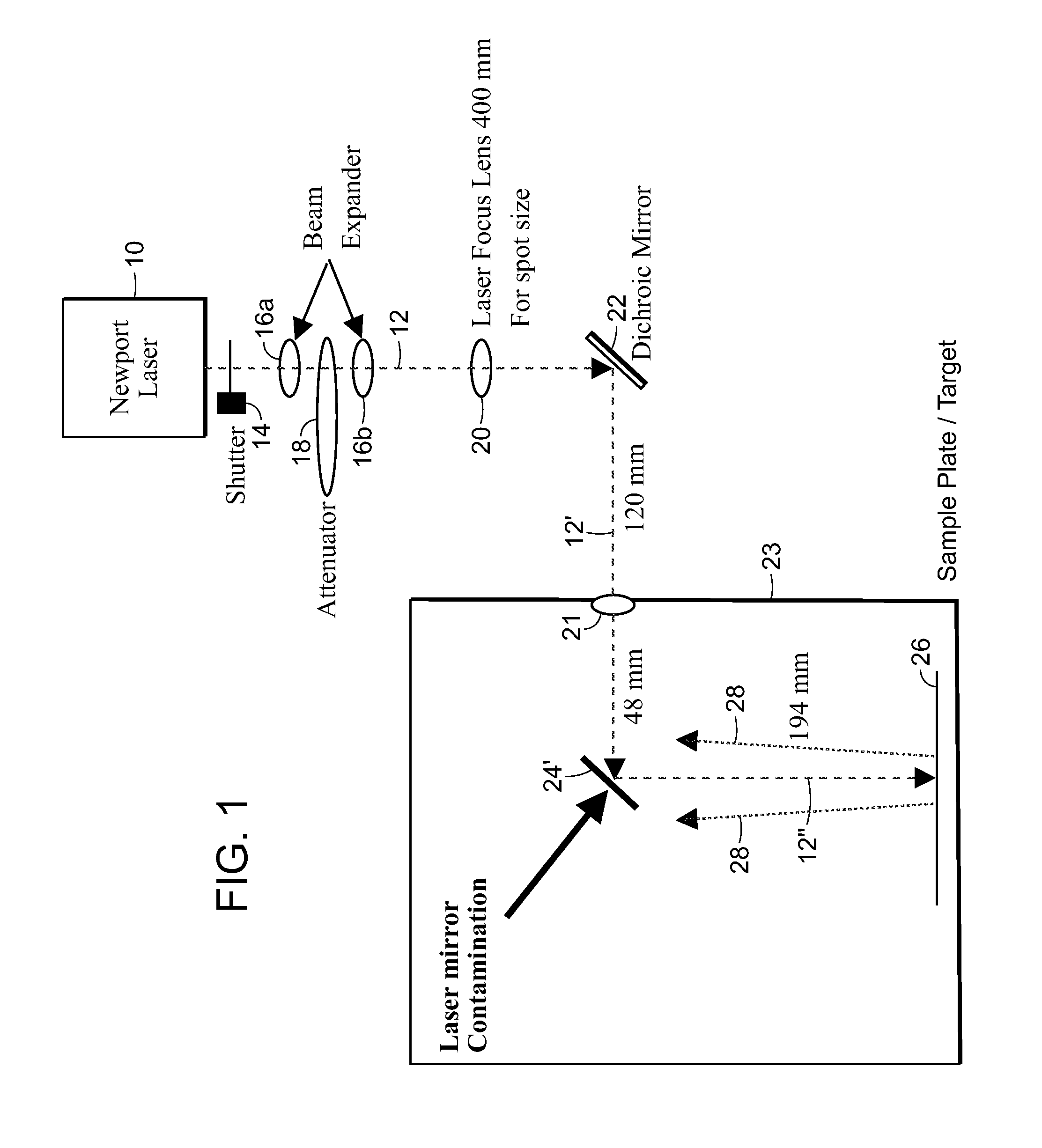
[0027]FIG. 1 is a schematic of an example of the optic components using laser desorption as the ionization mechanism, such as, for example, but not limited to, in a matrix-assisted-laser-desorption-ionization (MALDI) mass spectrometer. For the example illustrated a laser 10 passes a beam 12 through various optic components, including a shutter 14, beam expander lenses 16a and 16b, attenuator 18, and lens 20. In some embodiments of applicant's teachings the beam 12 is deflected by a dichroic mirror 22 to form beam 12′. Beam 12′ is directed through a view port 21 of a chamber 23 that holds a sample plate 26. Chamber 23 in various embodiments of applicant's teachings is at or near a vacuum.

[0028]After beam 12′ enters chamber 23 through view port 21, it is deflected by a mirror 24 to form beam 12″. Beam 12″ is thereby directed to the sample plate 26. When the laser beam 12″ hits the sample on the sample plate 26, a plume 28 of debris, or vaporized material, can be generated. For example...


PUM


Abstract

Applicant's teachings relate to apparatuses and methods of cleaning laser optical components, particularly in, for example, but not limited to, high throughput matrix-assisted laser desorption ionization (MALDI) applications. In accordance with various embodiments of applicant's teachings, the optical component is heated.

Description

CROSS REFERENCE TO RELATED APPLICATIONS[0001]This patent application claims priority to U.S. Provisional Patent Application Ser. No. 61 / 164,137, filed on Mar. 27, 2009, the entire disclosure of these patent applications are incorporated herein by reference.FIELD[0002]Applicant's teachings relate to apparatuses and methods of cleaning laser optical components, particularly in matrix-assisted laser desorption ionization (MALDI) applications.INTRODUCTION[0003]Generally, with analytical instruments using laser desorption as the ionization mechanism, such as, for example, in a matrix-assisted-laser-desorption-ionization (MALDI) mass spectrometer, the laser is often located remotely from the sample target. This accommodates the environmental operating conditions of the mass spectrometer, which can include, for example, vacuum conditions.[0004]Various conventional light transmission methods can be used to guide the light from the laser to the sample while maintaining the physical separatio...

Claims


Application Information

Patent Timeline
IPC IPC(8): B01D59/44G02B7/00
CPCH01J49/164G02B27/0006
Inventor LOYD, WILLIAM
Owner DH TECH DEVMENT PTE
Why Eureka
Try Eureka