Stabilizer for three wheel vehicle

a stabilizer and three-wheel technology, applied in the field of vehicles, can solve the problems of single front steering wheel and plural rear drive wheels and the instability of turning of scooter-type personal mobility vehicles having a single front steering wheel

Inactive Publication Date: 2010-09-30
FLOWERS IP
View PDF8 Cites 7 Cited by
  • Summary
  • Abstract
  • Description
  • Claims
  • Application Information

AI Technical Summary

Benefits of technology

[0012]The foregoing has outlined some of the more pertinent objects of the present invention. These objects should be construed as being merely illustrative of some of the more prominent features and applications of the invention. Many other beneficial results can be obtained by modifying the invention within the scope of the invention. Accordingly other objects in a full understanding of the invention may be had by referring to the summary of the invention and the detailed description describing the preferred embodiment of the invention.
[0013]The present invention is defined by the appended claims with specific embodiments being shown in the attached drawings. For the purpose of summarizing the invention, the invention relates to a stabilizer for a three-wheel vehicle. The three-wheel vehicle has a frame extending between a front portion and a rear portion. The front portion of the frame supports a front steering wheel with the rear portion of the frame supporting plural driving wheels for moving the three-wheel vehicle on a supporting surface. The improved stabilizer comprises a right and a left stabilizing wheel mounted on a right and a left side of the frame. The right and left stabilizing wheels are positioned above the supporting surface when the three-wheel vehicle moves in a straight direction on the supporting surface. The right and left stabilizing wheels engage the supporting surface when the vehicle is turned in a right and a left direction respectively for stabilizing the three-wheel vehicle. Although the stabilizer of the present invention is applicable to most three-wheel vehicles, the stabilizer of the present invention is especially suitable for use with a scooter type personal mobility vehicle.
[0014]In a more specific example of the invention, a front pivotable axis pivots the front steering wheel to steer the three-wheel vehicle. A front rotational axis rotates the front steering wheel upon movement of the three-wheel vehicle on the supporting surface. The front pivotable axis is perpendicular to the front rotational axis. A rear rotational axis rotates the plural drive wheels for moving the three-wheel vehicle on the supporting surface. The front pivotable axis is perpendicular to the front rotational axis and the rear drive axis.

Problems solved by technology

A scooter type personal mobility vehicle having a single front steering wheel and plural rear drive wheels exhibit instability during the turning of the three-wheel vehicle.
The turning instability of scooter type personal mobility vehicles having a single front steering wheel is also present in other three-wheel vehicles having a single front steering wheel.

Method used


Image

  • Stabilizer for three wheel vehicle
  • Stabilizer for three wheel vehicle
  • Stabilizer for three wheel vehicle

Examples


first embodiment

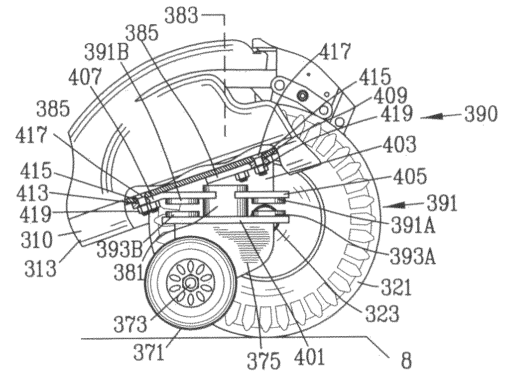
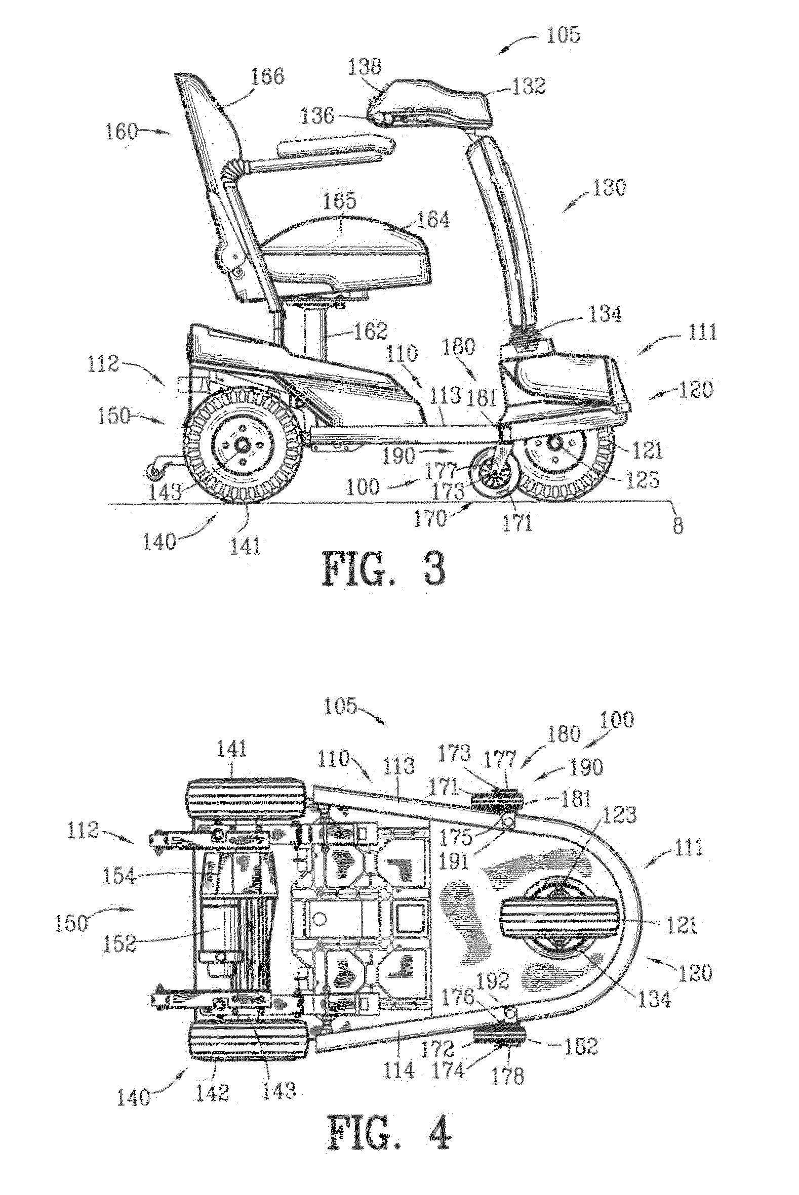
[0068]FIGS. 3-6 are various views of the stabilizer 100 of the present invention incorporated into a three-wheel vehicle 105 illustrated as a personal mobility vehicle. The three-wheel personal mobility vehicle 105 comprises a frame 110 comprising a front frame portion 111 and a rear frame portion 112 defined by frame members 113 and 114. The front frame portion 111 supports a front wheel assembly 120 including a steering mechanism 130 whereas the rear frame portion 112 supports a rear wheel assembly 140 including a drive unit 150.

[0069]The front wheel assembly 120 comprises a front wheel 121 rotatably mounted on a front axle123. The steering mechanism 130 is connected to the front wheel assembly 120. The steering mechanism 130 includes a tiller 132 comprising a handlebar assembly 134 connected to a front steering pivot 136. The front axle 123 is orientated in a generally horizontal plane whereas the front steering pivot 136 is orientated in a generally vertical plane and perpendicu...

second embodiment

[0083]FIGS. 15-19 are various views of the stabilizer 200 of the present invention incorporated into a three-wheel vehicle 205 illustrated as a personal mobility vehicle. Similar parts are labeled with similar reference numbers raised by 100.

[0084]The stabilizer 200 of the present invention comprises stabilizing wheels 270 shown as right and left stabilizing wheels 271 and 272. The right and left stabilizing wheels 271 and 272 are rotatably mounting by right and left rotational axle 273 and 274 to right and left brackets 275 and 276. The axels 273 and 274 are orientated in a generally horizontal plane.

[0085]Stabilizing wheel journals 280 are shown as right and left stabilizing wheel journals 281 and 282. The right stabilizing wheel journal 281 pivotably mounts the bracket 275 to the right frame member 213 of the front frame portion 211 of the frame 210 by a right connector 285. Similarly, the left stabilizing wheel journal 282 pivotably mounts the bracket 276 to the left frame membe...


PUM


Abstract

A stabilizer is disclosed for a three-wheel vehicle having a frame extending between a front portion and a rear portion. The front portion of the frame supports a front steering wheel and with the rear portion of the frame supports plural driving wheels. The stabilizer comprises a right and a left stabilizing wheel mounted on a right and a left side of the frame. The right and left stabilizing wheels are positioned above the supporting surface when the three-wheel vehicle moves in a straight direction on a supporting surface. The right and left stabilizing wheels engage the supporting surface when the vehicle is turned in a right and a left direction respectively for stabilizing the three-wheel vehicle while maintaining steering ability. Preferably, the stabilizer includes a right and a left director for directing the right and left stabilizing wheels in a forward direction when the right and left stabilizing wheels are positioned above the supporting surface. The invention is also incorporated into an accessory stabilizer unit adapted for mounting onto existing three-wheel vehicles.

Description

CROSS-REFERENCE TO RELATED APPLICATIONS[0001]This application claims benefit of U.S. Patent provisional application No. 61 / 210,974 filed Mar. 24, 2009 and U.S. Patent provisional application No. 61 / 269,399 filed Jun. 24, 2009. All subject matter set forth in provisional application No. 61 / 210,974 filed Mar. 24, 2009 and provisional application No. 61 / 269,399 filed Jun. 24, 2009 is hereby incorporated by reference into the present application as if fully set forth herein.BACKGROUND OF THE INVENTION[0002]1. Field of the Invention[0003]This invention relates to vehicles and more particularly to a stabilizer for stabilizing a three-wheel vehicle when the vehicle is turned in a right and a left direction.[0004]2. Background of the Invention[0005]A scooter type personal mobility vehicle typically comprises an elongated frame having front single or plural steering wheels and plural rear drive wheels. The front single or plural steering wheels are pivotably mounted on the front portion of t...

Claims


Application Information

Patent Timeline
Patent Type & Authority Applications(United States)
IPC IPC(8): B62D49/08B62K5/02B62K5/027
CPCB62H1/12B62K5/06B62K5/025
Inventor FLOWERS, MICHAEL J.
Owner FLOWERS IP
Why Eureka
Try Eureka