Fluid sensor, refrigerant leakage detection device, refrigeration system, and refrigerant leakage detection method

a technology of refrigerant leakage detection and fluid sensor, which is applied in the field of fluid sensor, can solve problems such as difficulty in pinpointing the location of refrigerant leakag

Inactive Publication Date: 2010-09-30
DAIKIN IND LTD
View PDF8 Cites 7 Cited by
  • Summary
  • Abstract
  • Description
  • Claims
  • Application Information

AI Technical Summary

Benefits of technology

[0012]In view of this, in this fluid sensor, a fluid holder for holding refrigerant or fluid resulting from refrigerant leakage is provided between the two electrodes, and the refrigerant or fluid resulting from refrigerant leakage that enters in between the two electrodes is held and accumulated in the fluid holder. Refrigerant leakage is thereby easily detected and the precision of refrigerant leakage detection can be increased, even if the amount of refrigerant leakage is extremely small.
[0046]When the electrostatic capacitances of each of the sensors differ, the time duration determined according to the electrostatic capacitance of the first sensor and the time duration determined according to the electrostatic capacitance of the second sensor are different, and the first and second time duration elapse signals indicating that each of the time durations have elapsed therefore begin to be outputted with different timings. In view of this, in this refrigerant leakage detection device, the first difference is calculated based on the length of time during which either the first time duration elapse signal or the second time duration elapse signal indicating the elapse of a time duration is outputted, i.e., based on the difference between the timing with which the first time duration elapse signal begins to be outputted and the timing with which the second time duration elapse signal begins to be outputted. Specifically, since the above-described length of time is equivalent to the change in electrostatic capacitance caused by the refrigerant or the fluid resulting from refrigerant leakage, it is possible to accurately single out the change in electrostatic capacitance caused by the refrigerant or the fluid resulting from refrigerant leakage, and refrigerant leakage can be detected with greater precision.

Problems solved by technology

However, in the method described above, it is difficult to pinpoint the location where refrigerant leakage is occurring.

Method used


Image

  • Fluid sensor, refrigerant leakage detection device, refrigeration system, and refrigerant leakage detection method
  • Fluid sensor, refrigerant leakage detection device, refrigeration system, and refrigerant leakage detection method
  • Fluid sensor, refrigerant leakage detection device, refrigeration system, and refrigerant leakage detection method

Examples


modification 1

(3) Modification 1

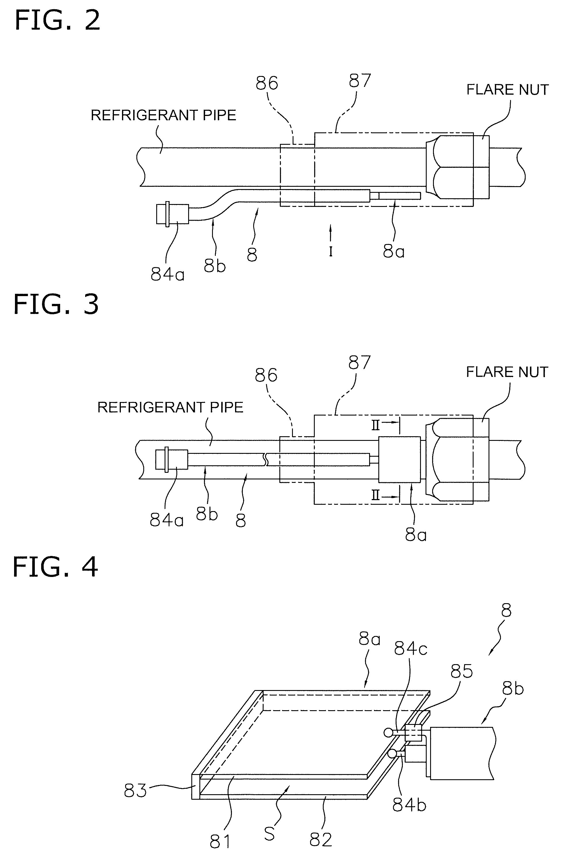
[0149]In the embodiment described above, a space S is merely formed between the two electrodes 81, 82 constituting the sensor main body 8a of the fluid sensor 8 as shown in FIG. 4, and since it is difficult for refrigerant or fluid resulting from refrigerant leakage to actively pool in between the two electrodes 81, 82 in this space S, there are cases in which refrigerant leakage cannot be detected if the amount leaked is extremely small, for example.

[0150]In view of this, in the fluid sensor 8 of the present modification, a fluid holder 88 for holding the refrigerant or the fluid resulting from refrigerant leakage is provided in the space S between the two electrodes 81, 82 as shown in FIG. 8, and the refrigerant or the fluid resulting from refrigerant leakage entering in between the two electrodes 81, 82 is held and collected in the fluid holder 88.

[0151]For example, when refrigerator oil is to be the fluid resulting from refrigerant leakage and is actively held ...

modification 2

(4) Modification 2

[0153]In both the embodiment described above and Modification 1, the sensor main body 8a of the fluid sensor 8 was provided to a portion in the refrigerant circuit 10 where refrigerant leakage detection was performed, but depending on the situation, there are cases in which the sensor main body 8a must be placed in proximity to the portion in the refrigerant circuit 10 where refrigerant leakage detection is performed, yet separate from the portion in the refrigerant circuit 10 where refrigerant leakage detection is performed.

[0154]In such cases, a fluid-guiding member 89 may be provided for leading refrigerant or fluid resulting from refrigerant leakage from the portion in the refrigerant circuit 10 where refrigerant leakage detection is performed to the sensor main body 8a, and the refrigerant or fluid resulting from refrigerant leakage may be actively led between the two electrodes 81, 82.

[0155]For example, using the fluid sensor 8 in Modification 1 as an example...

modification 3

(5) Modification 3

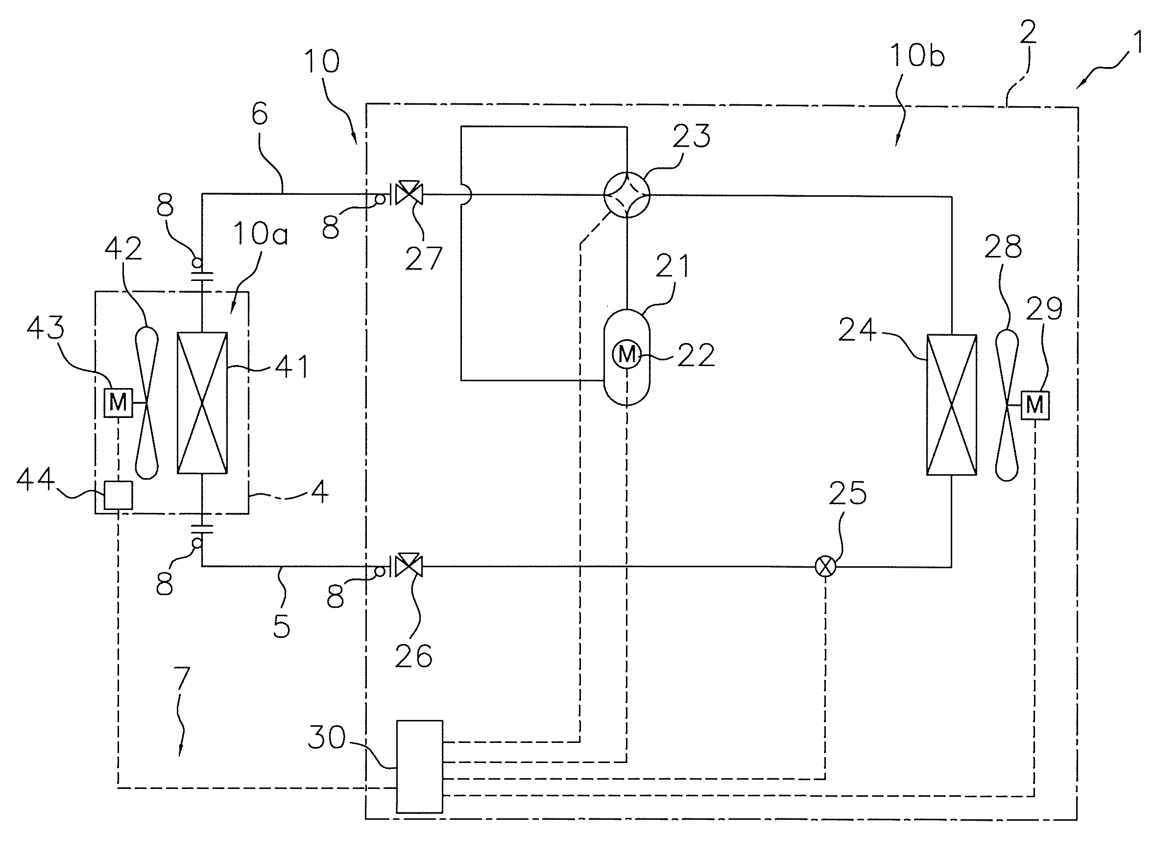
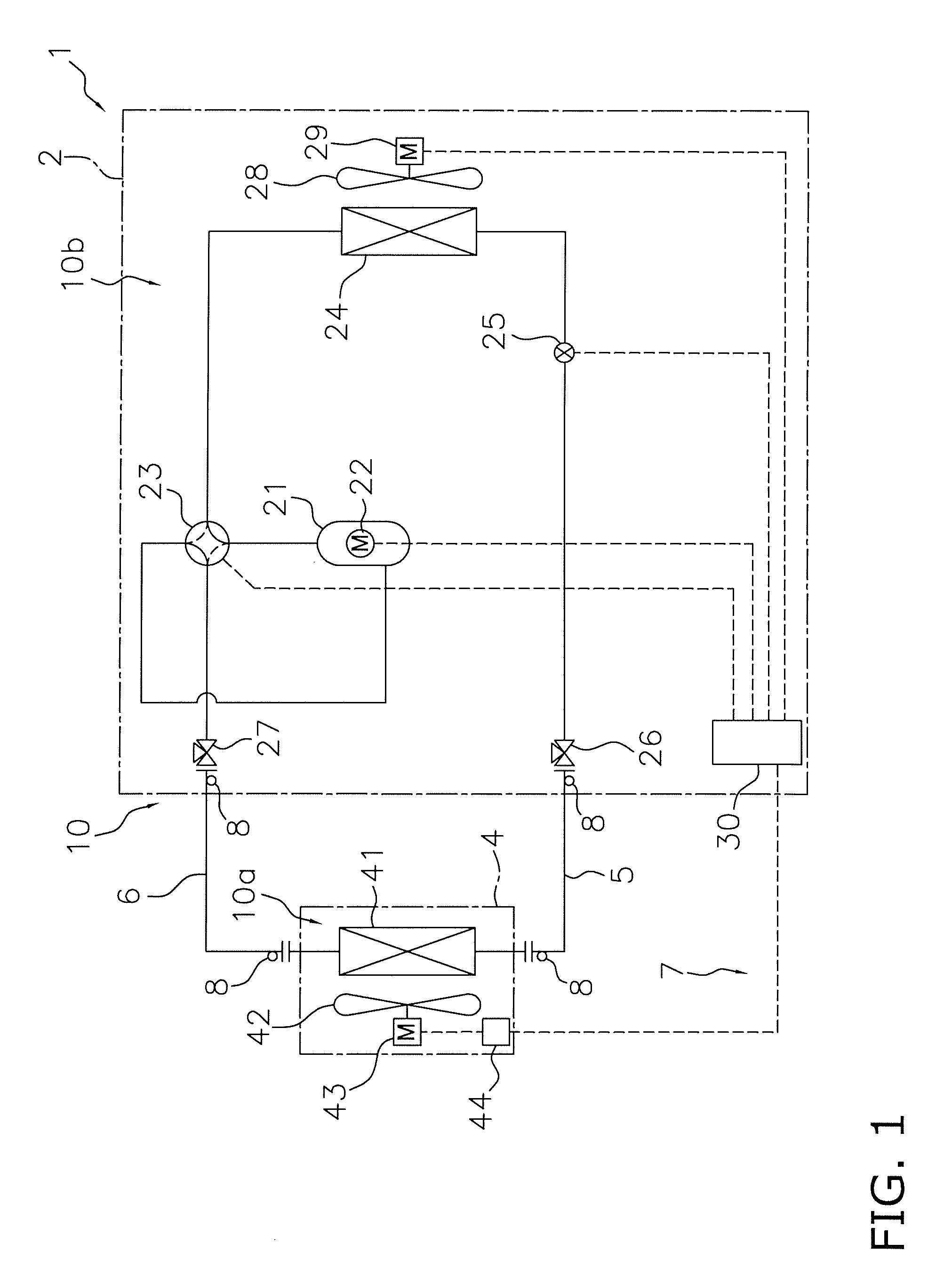
[0157]In the embodiment described above as well as Modifications 1 and 2, the sensor main body 8a with a flat plate-shape structure is used as shown in FIGS. 2 to 4, 8, and 9, but the sensor main body 8a may also have a structure that can be attached so as to wind around the pipes or pipe joints constituting the refrigerant circuit 10.

[0158]For example, one possibility is to attach a sensor main body having a fluid holder 88 provided in the space S between the two electrodes 81, 82 so that the sensor main body winds around a pipe, as is the case with the sensor main body 8a of the fluid sensor 8 of the present modification shown in FIGS. 10 and 11. This sensor main body 8a may also be attached so as to wind around a pipe joint rather than a pipe.

[0159]It is thereby possible with the fluid sensor 8 of the present modification to effectively lead refrigerant or fluid resulting from refrigerant leakage in between the two electrodes 81, 82, and it is therefore possible...


PUM


Abstract

It is possible to detect refrigerant leakage while pinpointing the location where refrigerant leakage is occurring in a refrigerant circuit of a refrigeration system. A fluid sensor (8) is a fluid sensor for detecting refrigerant leakage from a refrigerant circuit (10), wherein the fluid sensor includes a sensor main body (8a) having two electrodes (81, 82) spaced apart, and the fluid sensor (8) is configured such that the fluid sensor (8) is capable of being connected to an impedance measurement device (9) for measuring impedance between the two electrodes (81, 82).

Description

TECHNICAL FIELD[0001]The present invention relates to a fluid sensor, and particularly relates to a fluid sensor and refrigerant leakage detection device for detecting refrigerant leakage from a refrigerant circuit of a refrigeration system. The present invention also relates to a refrigeration system comprising a fluid sensor and a refrigerant leakage detection device, and to a refrigerant leakage detection method that uses a fluid sensor.BACKGROUND ART[0002]In one example of a method for detecting refrigerant leakage from a refrigerant circuit of a refrigeration system, a refrigerant quantity charged in a refrigerant circuit is calculated from various operative state quantities, and refrigerant leakage is detected from this calculated refrigerant quantity.[0003]<Patent Document 1>[0004]Japanese Laid-open Patent Application No. 2007-163099DISCLOSURE OF THE INVENTION[0005]However, in the method described above, it is difficult to pinpoint the location where refrigerant leakage...

Claims


Application Information

Patent Timeline
Patent Type & Authority Applications(United States)
IPC IPC(8): G01R27/08
CPCF25B13/00G01M3/188F25B2500/222F25B49/005
Inventor SASAKI, YOSHINARIYAMAGUCHI, TAKAHIROYONEMORI, TSUYOSHIYOSHIMI, MANABUXU, YOUYOU
Owner DAIKIN IND LTD
Why Eureka
Try Eureka