Method and apparatus for leak detection in horizontal cylindrical storage tanks

a technology for horizontal cylindrical storage tanks and leak detection, which is applied in the direction of measurement devices, structural/machine measurement, instruments, etc., can solve the problems of direct measurement of leaks, leak detection process, and exposure of tanks to failure, so as to avoid the danger of transporting and storage of drained products, the volumetric leak rate is precise and cost-effective, and the effect of avoiding the danger of leakag

Active Publication Date: 2013-06-25
MASS TECH
View PDF25 Cites 1 Cited by
  • Summary
  • Abstract
  • Description
  • Claims
  • Application Information

AI Technical Summary

Benefits of technology

[0016]In view of the foregoing, it is an object of the present invention to provide a storage tank leak detection apparatus with a very low detection threshold that maybe used in an efficient manner thereby preserving industrial and environmental resources.
[0017]It is another object of the present invention to provide an apparatus for precise storage tank leak detection.
[0018]It is another object of the present invention to provide an apparatus for cost-effective storage tank leak detection.

Problems solved by technology

That is, storage tank owners are willing to invest huge sums of money in both the maintenance and inspection of such tanks.
As one could imagine, there are a wide range of problems associated with measuring and determining storage tank integrity, particularly in horizontally disposed cylindrically shaped tanks.
Such positioning and shape greatly complicates direct measurement of leaks by typical means.
By relying on secondary indications of leaks, typical leak detection methods compromise the leak detection process, expose the tank to failure due to the applied test pressure or vacuum and open the possibility that a real leak is masked by the very application of the test.
Also, such methods do not monitor loss by vaporization.
Use of a typical mass measurement based leak detection system in horizontal cylindrically shaped tanks without a direct and continuous measurement of the density of the tank's contents is fraught with the possibility for incorrect or inconclusive leak determinations.
However, the recognized difficulties in measuring, determining and preventing storage tank leaks does not mitigate the duties or liabilities imposed on responsible parties.
Tremendous environmental and economic consequences and the threat of litigation and clean up costs associated with storage tank leaks force responsible parties to invest large sums of money in the maintenance and inspection of the tanks.
Tank inspections are costly with respect to the amount of money spent, the danger presented to the inspectors and the environment, and production downtime.
In fact, these inspections often remove a tank from service for more than one month.
The threat of liability also forces responsible parties to spend money unnecessarily for the maintenance of these tanks.
Currently, responsible parties are, in some countries, being incarcerated as a direct result of storage tank leaks.
These leaks have contaminated surrounding ground water, some of which serves as drinking water for local residents.
Each day the shuttered facilities remain inoperative adds to an already tremendous amount of money lost.
Similarly there are no known systems for direct and quantitative measurement of potential leaks in horizontally disposed cylindrical tanks of 50,000 gallon capacity and larger.
Storage tank leak detection systems are known in the art; however, these products are fraught with problems.
The present systems are imprecise, or provide erroneous data for any or all of reasons including: the consistency of the soil acting as the tank's foundation, the temperature (thus density) stratification of the tank's fluid contents, product loss as vapor, extraneous noise sources, the effects of ground water table level, previous soil contamination, and / or tank shell dynamics.

Method used


Image

  • Method and apparatus for leak detection in horizontal cylindrical storage tanks
  • Method and apparatus for leak detection in horizontal cylindrical storage tanks

Examples


Embodiment Construction

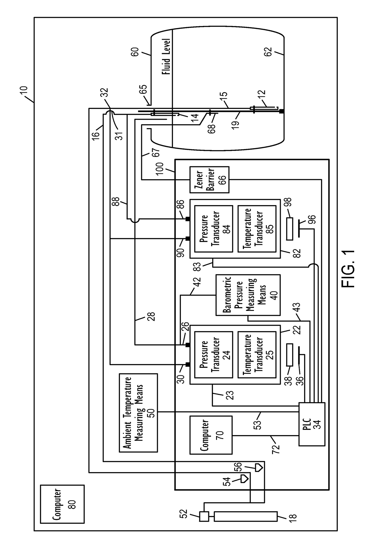
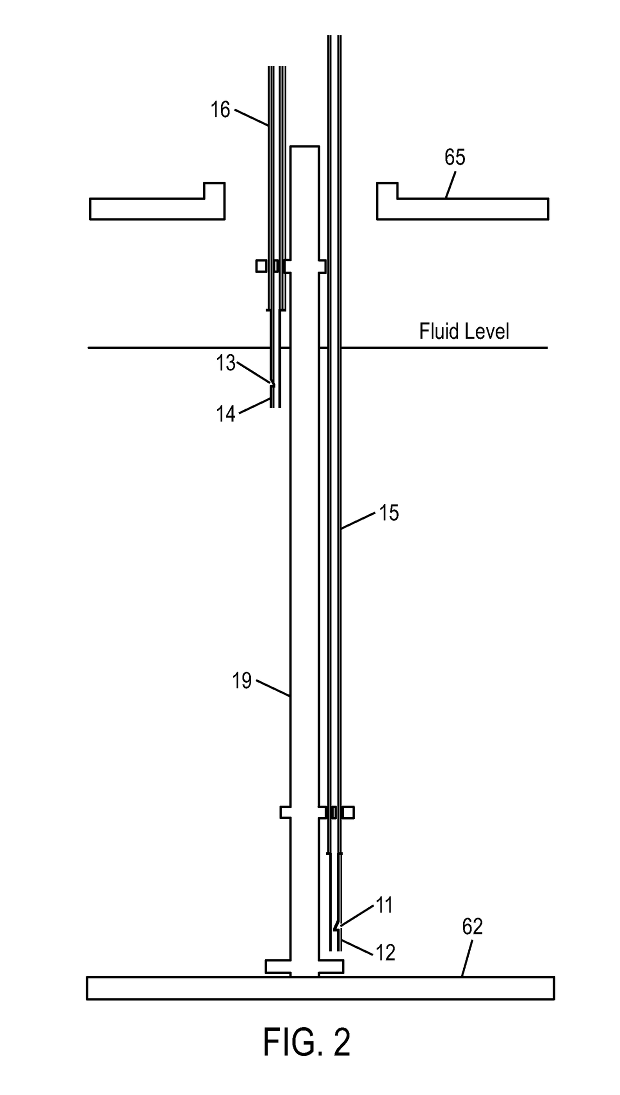
[0064]In the drawings and the description that follows, referring to FIGS. 1 and 2, a preferred embodiment of a storage tank leak detection system according to the present invention is generally designated as system 10.

[0065]Referring to FIG. 1, an embodiment of the present invention is shown to include an inert gas pressure reduction 52 and flow rate regulators 54 and 56, which provide a clean and steady supply of an inert gas such as nitrogen, from a compressed cylinder 18 to a plurality of in-tank bubblers 12 and 14 via bubbler tubes 15 and 16, respectively.

[0066]Support rod 19, supports releasably attached in-tank bubblers 12 and 14, and is placed in the horizontally disposed cylindrically shaped storage tank (“tank”) and removably attached to the bottom of the tank. Support rod 19 is preferably constructed from materials with physical and chemical properties resistive to expansion caused by temperature change. In this embodiment support rod 19 is constructed from Super-Invar bu...


PUM


Abstract

A storage tank leak detection system for detecting and measuring very small leaks in large horizontal cylindrical storage tanks. Embodiments include two highly precise quartz crystal type pressure transducers held at a constant temperature. A bubbler to achieve access to the hydrostatic pressure at the tank bottom and just below the liquid surface. First transducer and bubbler are used to measure fluid mass while second transducer and bubbler are used to measure fluid density then used in combination with data correction and regression techniques to yield a storage tank leak detection system for use in horizontal cylindrically shaped tanks with an extremely low leak detection threshold.

Description

CROSS-REFERENCE TO RELATED APPLICATIONS[0001]This application claims benefit to U.S. Provisional Patent Application No. 61 / 154,645, filed Feb. 23, 2009, the contents of which are incorporated by reference herein in their entirety.BACKGROUND OF THE INVENTION[0002]1. Field of the Invention[0003]The present invention is directed towards a method and apparatus for providing a safe, precise, and cost-effective storage tank leak detection system and more particularly, to a method and apparatus wherein the containment integrity of a storage tank is determined by mass measurements of the stored product.[0004]2. Background Information[0005]Storage tanks play a vital role in today's economy. The economy, on a global scale, depends on the proper function of these tanks as they are prevalent in several industries and virtually every geographical region in the world. In light of the vital role these storage tanks play, the integrity of the tanks is placed at a premium. That is, storage tank owne...

Claims


Application Information

Patent Timeline
Patent Type & Authority Patents(United States)
IPC IPC(8): G01M3/32
CPCG01M3/3263G01M3/00
Inventor WOLFORD, JIMMYWOLFORD, JR., BERNIELOCKERD, CLARKSLAUGHTER, RICKY
Owner MASS TECH
Why Eureka
Try Eureka